 Nobody will deny that the Apple iPod is single-handedly responsible for a massive shift in the portability of music. Sure, the Walkman and Discman were important components in the history of portable media players, but those technologies supported existing music formats in the form of cassettes and compact discs. The iPod embraced digital media file formats, and though Apple offers its own compression formats in the form of AAC and ALAC, the iPod made MP3 files and digital audio downloads immensely popular.
How the iPod Changed Music
 In the ’80s and ’90s, going to the record store was a thing. Music enthusiasts knew when new albums would be released and would plan their schedules around making time to be at the store early on those mornings so they’d be the first to get a copy. Fast forward to the 2000s, and access to new music is as simple as a click of your computer mouse or a tap on your phone and a short wait while the album downloads to your desktop or your smartphone. This convenience eventually affected the record store business model, and we’ve since seen Tower Records, Camelot Music, Tape World, Sam Goody and Canada’s Sam the Record Man fade away.
The real benefit of the iPod and subsequently the iPhone was their ability to store a large amount of music in a convenient and easily accessible package. This convenience spelled the demise of the CD changer and the advance of support for direct compatibility with Apple devices. Companies like Clarion launched graphical interfaces around 2005 that provided an iPod-like experience in the screen of their multimedia receivers. Now, almost every source unit on the market offers Made for iPod/iPhone/iPad connectivity.
What is the MFi Program?
 Apple’s MFi (Made for iPod/iPhone/iPad) program is a licensing program for companies that develop hardware or software that is designed to communicate digitally with these portable media devices. The original program, called Made for iPod, was launched in 2005 at the Macworld Expo and has evolved to include AirTunes wireless streaming, wireless game controllers and, most recently, devices intended for use with the HomeKit system that mimics Google Home and Alexa functionality.
As a manufacturer, companies developing products under the MFi agreement are provided with technical resources such as connector information, component specifications and software protocols required to make their devices work. The caveat is that any device that will use Apple certified compatibility icons must pass a stringent product certification process. Several members of the Best Car Audio team have intimate experience with this certification process, and we can tell you that obtaining certification is often a difficult challenge. If you follow the industry carefully, you’ll be able to think of many products that were delivered to the market late because of changes required by Apple.
How Does MFi Benefit Consumers?
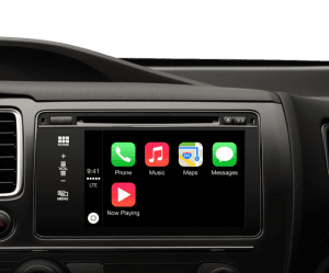 The goal of the MFi program is to ensure that consumers are provided with a predictable experience. Functions may not always work the way you want, but they will work the same on every product that has been through the MFi certification program. Though iPod and iPhone connectivity is a relatively simple process, the recent popularity of CarPlay is where the standards really tax the resources of those who are developing products. Apple tests screen geometry, icon colors and the position of volume function overlays. It has stringent hardware requirements that include strict USB connectivity testing and requirements for an onboard gyro.
When you go shopping for a CarPlay device for your vehicle, you’ll want to look for products that are MFi certified. Currently, they are available from Alpine, Clarion, JVC, Kenwood, Pioneer and Sony, according to Apple’s CarPlay website.
What About Devices That Aren’t MFi Certified?
 In researching this article, we talked to several companies that develop products under the MFi program. One of them mentioned that they had seen a list of blacklisted device keys in a preview of iOS 12.1 for the iPhone Xs. What does this mean? Any device that connects to an iPod, iPhone or iPad through the Lightning connector must include a small microcontroller that includes a software key. Think of this key like a digital serial number. These microcontrollers are found on all Lightning cables as well as headphone and video adapters.
When Apple launched iOS 7 in September 2013, many unlicensed Lightning cables stopped working and users got a message stating that “this cable or accessory is not certified and may not work reliably with this iPhone.” Though there seemed to be some workarounds to get those cables to charge your phone, it was a brief look at what Apple can do regarding protecting its intellectual property.
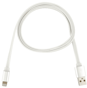 Recently, we’ve seen an influx of inexpensive Lightning cables and charging adapters available for sale at the checkout counter of local gas stations, variety stores and hardware stores. While the price and convenience of these cables are alluring, we want to caution our readers about using devices that aren’t specifically approved by Apple.
Adding CarPlay to Your Vehicle
If you have a vehicle with a color touchscreen, who wouldn’t want to be able to add the convenience and safety of CarPlay to the vehicle? Several companies like BMW and Hyundai have made upgrades available for purchase to add this functionality to platforms that did not come with CarPlay from the factory.
Several third-party options claim to add CarPlay to almost any vehicle with a USB port. We can’t speak directly as to whether these products are MFi certified, but you will want to make sure they are before you invest in them. Because we know that Apple tracks device keys, any unauthorized products could be rendered non-functional with a simple update from Apple.
The next time you are shopping for a new Lightning cable or an accessory for your iPhone, iPod or iPad, make sure you look for the MFi certification logo on the packaging. This logo will ensure that the new device will continue to function reliably with each new iOS update from Apple. For more information, visit your local mobile electronics retailer and ask about the products they offer that are MFi certified.
This article is written and produced by the team at www.BestCarAudio.com. Reproduction or use of any kind is prohibited without the express written permission of 1sixty8 media.
 Let’s face it, most of us aren’t really happy with the
 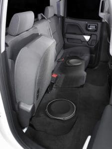 Even the most exotic of factory-installed sound systems cannot produce amazing bass. For most of us, the speakers in the doors don’t play much below about 50Hz. This means we are missing out on more than an octave of the most fun part of our music.
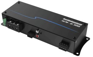 Beyond not having enough bass in a factory audio system, the next most common complaint is that the system won’t play loudly enough. While the speakers in your car are limited in their capabilities, the most common issue is a lack of power from the radio or
 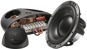 If you have read any number of our articles here at
 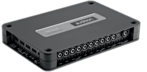 For too long, adding a signal processor has been considered the icing on the cake when it comes to premium audio system design. The reality is, as soon as your budget allows for it, adding a processor can dramatically improve the performance of even a modest installation.
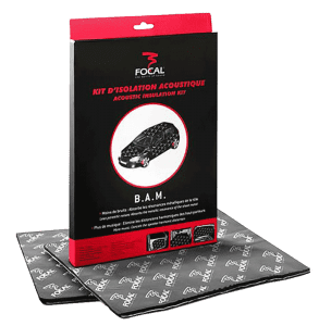 If you have ever upgraded a sound system by switching from an inexpensive amp to a great one, you may have noticed there is less background noise or hiss. When listening to music in our vehicles, we need to try and ignore wind and road noise and sound from the engine and exhaust system. Having your local car audio specialist retailer add a layer of
 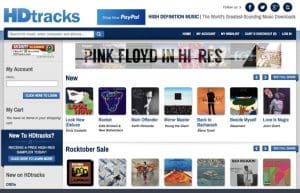 No, we aren’t dissing your gangster rap or John Fogerty CDs. There has been a trend of late to focus on high-resolution audio files like FLAC and DSD. While the mechanical limits of these file formats dramatically exceed the listening limits of all humans, the improvement in recording and mastering equipment required to create these recordings is of excellent quality. In short, even within the standard 20Hz to the 20kHz range, high-res audio files sound better because they are created better.
 The easiest upgrade is a
 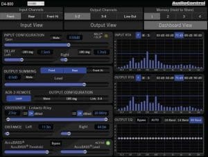 Lots of us like to install car audio equipment at home in our driveway. Do-it-yourself car audio has been popular since the 1970s and always will be. The problem is, it takes more than a solid understanding of electrical theory and physics to install and configure a modern audio system. Qualified installers use tools like real-time analyzers to set crossovers and adjust polarity. They use oscilloscopes to match the amplifier sensitivity settings to the source unit. Investing in this gear is often out of reach for most do-it-yourselfers and often overlooked. If every aspect of your audio system isn’t optimized, you are short-changing yourself on performance.
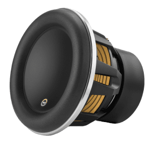 How’s that for a confusing idea? What we are talking about is replacing your existing audio equipment with even better products. Let’s say you had a set of $250 components installed in the doors of your car a few years ago, and the system is tuned to optimize those speakers with a digital signal processor. If you upgrade those to a set of $1,600 components and have the system retuned, the difference will be night and day. Your music will be clearer and more detailed. You’ll be able to pick out subtleties that were otherwise lost. Think of upgrading to amazing speakers like cleaning your glasses: Everything will suddenly become crystal clear. The same applies to upgrading your subwoofers. There is a lot of information in the bottom few octaves of your music. A better sub will recreate your bass with dramatically improved realism.
 In the ’80s, ’90s and early part of the 2000s, upgrading the car stereo system in your vehicle was a relatively simple process. You’d start by picking out a new radio that offered the features you wanted and add a set of speakers to improve the sound of the system. Pretty much anyone with a basic understanding of electrical systems could use a wire harness adapter to install the radio, and the speaker installation was usually a drop-in upgrade, save for having to crimp on some spade connectors.
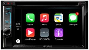 Fast-forward to 2010 and beyond, and the world of
 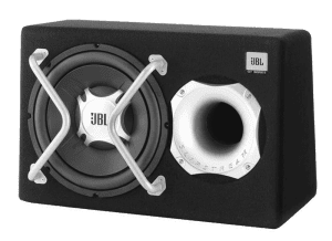 When you take your new car to a shop for a sound system upgrade, there are a few steps required to ensure you will get the performance you want from the system. The first should be a series of questions from the salesperson about how you enjoy your music. Do you listen at high volume levels? Do you like lots of bass? Some will ask you what kind of music you listen to to help understand your goals for your audio system. For the truly dedicated, the questions should include a query about what you hope to improve by upgrading the system. A visit to your vehicle can often provide valuable insight into what’s missing. If you have the bass turned up on the factory radio, you may benefit from a
 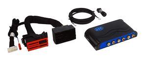 Where the expertise of a mobile electronics specialist retailer shines is in knowing how your factory stereo works and, subsequently, how to upgrade it. Remember the signal processing we talked about at the beginning of the article? If a shop sells you a new set of speakers without addressing this tuning, you may not like the results. There are three options available to deal with this processing. If you can, a new radio and potentially a new amplifier will eliminate the tuning. Audio interfaces include the PAC AmpPRO, iDatalink AR, Axxess AX-DSP or one of the many ZEN-Audio solutions from Nav-TV. Finally, you can add an amplifier with a digital signal processor to correct the tuning for the new speakers. There’s no “best” answer to your upgrade needs, as each vehicle and client’s goals differ.
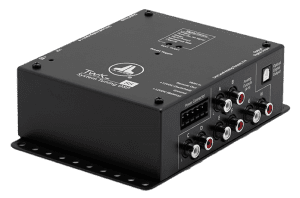 Before you balk at the cost of adding a DSP and amp to your
 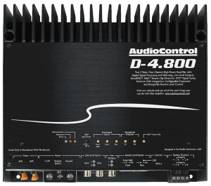 Let’s look at how we handle the tuning in the vehicle. You’ll need an amplifier with a built-in DSP. There are lots of compact solutions available from companies like JL Audio, Mosconi, Helix, Audison, AudioControl, Sony, Alpine and Kicker. A suitable
 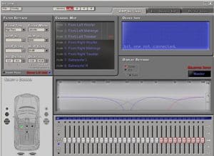 Take a deep breath. Talking about spending thousands of dollars on a speaker upgrade might scare a lot of people. The question is, are the upgrades worthwhile? When executed by a properly trained technician, the answer is unquestionably yes! Not only will new speakers play louder, they produce less distortion to make your music clearer and more detailed. The signal processor can be used to fine-tune the system to provide the overall sound balance you want. Most people enjoy smooth and natural midrange with some accentuation in the midbass region and a little more in the bass region. Your technician can
  In 1982, Michael Knight was able to talk to his 1982 Pontiac Firebird and ask it for navigation directions. Of course, watching “Knight Rider” meant that we understood that KITT was make-believe. Fast-forward 35 years, and talking to our vehicles is now a reality, thanks to our
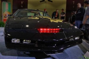
 Long before we had to worry about looking at maps on our phones, we had to deal with the issue of people talking on their phones while driving. Distracted driving is a serious issue and is the cause of many accidents and fatalities. In 2013, more than 3,000 people were killed because of distracted driving. In 2015, more than 391,000 injuries were caused by driver distraction.
 We started talking about asking our phones for directions. Portable
  Unlike the voice recognition system built into portable navigation devices that listened for specific phrases or requests, Apple’s Siri and Google’s Voice Assistant can interpret common language communication to perform commands or execute requests. “Navigate to” has been replaced with “find me a,” “take me to” or “get directions to” whatever address or location you want. These systems capture what you say, analyze the content on their servers, then send the required commands back to the phone.
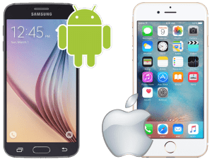 Apple CarPlay and Android
  Automakers are working to allow our vehicles to talk to each other in order to reduce traffic congestion and the chance of accidents. For this to happen, your car or truck needs to know where all the vehicles around it are located and where they are going. The hardware exists today to make this happen, but the communication networks aren’t fast enough to implement the system.
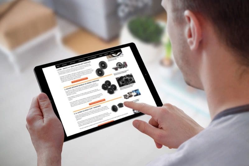 Not too long ago, we saw a discussion about an article called “The 12 Best Tweeters (Reviews & Ultimate Buying Guide 2018).” Being curious, we decided to check the article out to see what criteria they used to choose the products and how they tested them. Much to our dismay, there were no criteria, nor was there any testing or a simple performance review. So, what was going on? Read on and we’ll explain why you should be wary of Top 10 lists.
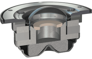 In a formal product review, the goal is to explain the features and benefits of a product. In the case of a tweeter, a review would include a detailed explanation of the product design, an explanation of the materials used to build the device, lab-based measurements of the output and a listening test. Of course, a summary of the key benefits and drawbacks of the design would give readers the opportunity to decide for themselves, based on their application and budget, if that product was suitable for their application.
 The formal definition of clickbait is content or a title that encourages visitors to click on a link to a particular page or video. A few examples would be “How to get free beer” or “You won’t believe how great these speakers sound.”
 Now that you know what should be in a product review, or in this case, a product comparison, and clearly, that hasn’t been provided, why did they go to all the trouble of making the website and the article? The answer is to make money. You see, each product includes a link to “check the latest price on Amazon.” If you hover your mouse over the link, you’ll see that the website name is included as a tag in the link. This is called an associate link. If you follow the link and purchase the product, the website that provided the link gets a kickback from Amazon. Depending on the category, the kickback can be anywhere from 1 percent to 10 percent of the selling price. In terms of the website making money, it’s well worth the effort.
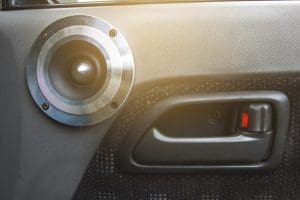 When it comes to helping you choose the best possible products for your