 Welcome to our new series about understanding product specifications. Our goal in these articles is to help you understand what the amplifier power ratings mean when you start to compare solutions. We’ll not only explain which numbers are good, but we’ll include a detailed description of what each specification means, how it’s measured and how it affects what you hear or experience. To start the series, let’s look at amplifiers. It’s a subject we’ve chosen because people tend to focus on amplifier specifications more than anything else when shopping.
Why Your Car Audio System Needs Power
 Without a doubt, the most popular specification that consumers look at when purchasing a car audio amplifier is its power rating. An amplifier takes the small signal from your source unit and increases it in voltage and current to drive a low-impedance speaker. In a nutshell, the more power you have, the more loudly you can play your car stereo system before the signal going to the speakers distorts. The limit of how much power is required is determined by the power handling specifications of the speakers in the vehicle, their cone excursion limits and their distortion characteristics. We’ll look at those limits in a future article about speaker specifications.
How We Measure Power
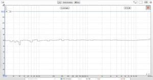
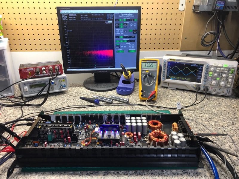
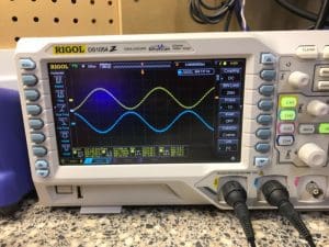
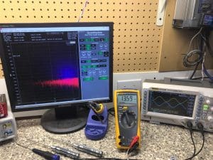
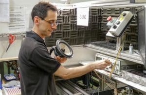
When an amplifier is set up in a lab to measure power, it’s typically connected to a power supply and a set of load resistors. Many manufacturers use test equipment from companies like Audio Precision to measure the distortion characteristics of the output signal to determine the point at which you would hear the distortion.
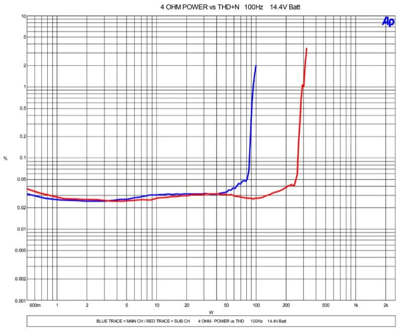
The Consumer Technology Association (formerly the Consumer Electronics Association) has established a standard for the power and signal-to-noise ratio measurements of car audio amplifiers called CTA-2006-B (formerly CEA-2006-B). The specification states that power measurements are to be taken with the amplifier powered with a voltage of 14.4 volts, and the measurement is taken into a specified load (typically 4 ohms) with no more than 1 percent total harmonic distortion and noise, across the entire bandwidth of the amp.
 In layman’s terms, the amp must perform as well producing bass as it does high-frequency information, and the specified power rating cannot include large amounts of distortion. While the 14.4V rating is somewhat high, it establishes a level playing field from which consumers can compare results.
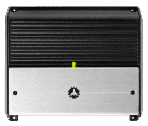
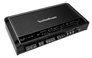
Several companies include additional power measurements to highlight different characteristics and performance features of their products. JL Audio, for example, includes output power ratings tested at 12.5 volts. Rockford Fosgate includes dynamic power ratings taken using the IHF-202 standard. Essentially, the dynamic power rating demonstrates the reserve capacity of an amplifier’s power supply to drive transient signals that last no more than 20 milliseconds.
Do Some Manufacturers Cheat?
 If you don’t see the CTA-2006 logo associated with a product you are considering, there are several ways that the numbers may not be directly comparable with other options. One easy way to inflate numbers is to increase the supply voltage to the amp. Depending on the design of an amplifier’s power supply, each additional volt provided to that power supply could theoretically increase the amplifier’s output by about 0.6 dB. That would be like a 100-watt amp being able to make about 115 watts.
Not specifying a distortion rating is another great way to fudge the numbers. Most Class AB amps can produce 60 percent to 70 percent more than their 1 percent rated power if they are driven hard into clipping. Of course, the music no longer sounds like music and you run the risk of damaging speakers because they’ve been over-powered.
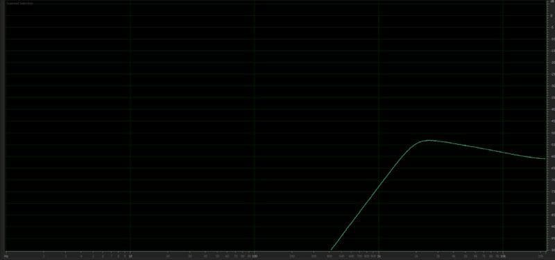
Finally, some amplifiers have problems with producing power at the extreme ends of the frequency spectrum. To be compliant with the spec, the amp needs to make the rated power level at 20 Hz through 20 kHz, or whatever the upper limit is for the design.
Do Amplifier Power Ratings Really Matter?
 If you are shopping for an amplifier, the power rating does nothing to tell you about the quality of one amplifier compared to another. You don’t need 100 watts to drive your tweeters and you certainly won’t be happy with a 25-watt amp driving a subwoofer in your car.
When you are comparing amplifiers, don’t get your knickers in a knot over a few watts. This applies specifically to amplifiers that come with birth certificates (documentation that states a particular amplifier’s power production capabilities). You can’t hear the difference between an amp that makes 300 watts and one that makes 305 watts. That difference would be a mere 0.07 decibels. You will hear a difference between a subwoofer amp that produces 100 watts and one that can deliver 300 watts.
We’ll add a note about “how things work” here. To increase the output of your audio system by 3dB, you need an amp that can produce twice as much power. So, to go from 90 dB in your car, you need twice as much power from the amp to raise the volume to 93dB and twice as much again to get to 96dB.
Shopping for a Car Audio Amplifier
When it’s time to go shopping for a car audio amplifier to provide more power to your speakers, drop into your local car stereo shop and speak with one of their product specialists. They can help you determine how much power is appropriate for the system you have in mind and choose an amp that sounds great and works with your budget.
This article is written and produced by the team at www.BestCarAudio.com. Reproduction or use of any kind is prohibited without the express written permission of 1sixty8 media.
 If you are an avid car audio enthusiast, it’s likely that you’ve seen photos of or heard systems that use high-efficiency pro audio style speakers. These drivers were designed for PA systems at concerts and can produce impressive output levels with moderate levels of power from an amp. In this article, we are going to look at the benefits and drawbacks of using pro-sound speakers in applications like a
 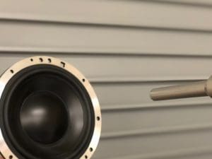 Before we dive into the differences between conventional car audio speakers and high-efficiency speakers, let’s take a quick look at the definition of speaker efficiency and what design features change this value.
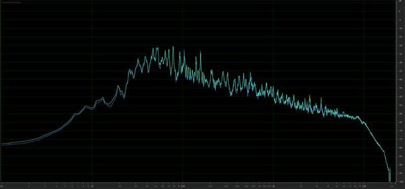
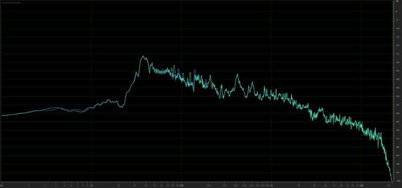
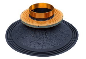 Several technical design details determine speaker efficiency. One of the biggest factors is the weight of the cone and voice coil assembly. A lightweight cone assembly is easier to move and typically produces more output with less power. The drawback of this low-mass design is that the resonant frequency of the speaker will be higher and the driver won’t produce anywhere as much bass. This is the basic trade-off between conventional car audio speakers and pro-sound drivers.
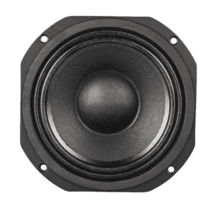
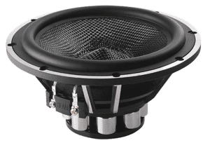 Let’s compare two popular 6.5-inch woofers, both intended for car audio applications. Speaker A is a conventional
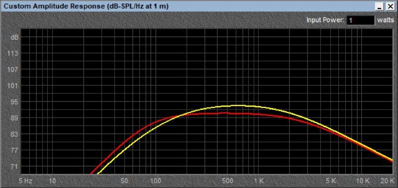
 If you have plans to add a dedicated woofer to the saddlebag or trunk on your bike, and can find one that will play up to 150 or 200 Hz without significant distorting, then pro-style high-efficiency speakers may be a good option if all that matters is how loudly the system will play.
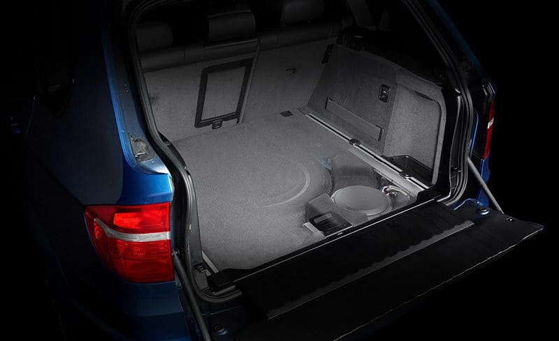 Did you know that in Europe, there aren’t nearly the number of qualified
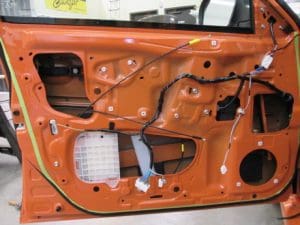
 When you say the word subwoofer to someone, they often envision someone driving down the street with a wall of woofers, shaking windows and being otherwise annoying. The reality is, adding a subwoofer to even a premium
 Understanding how to recreate
  At the most fundamental level, sounds are vibrations that travel through air and other mediums. These vibrations are detected by our ears, which in turn convert them to minute electrical signals that our brains interpret.
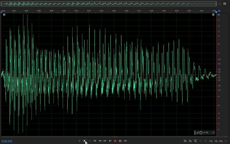
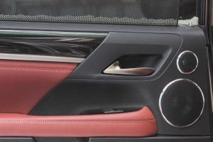 To achieve this goal, you need at least a two-way speaker system. Because no single speaker can reproduce the entire audio spectrum (from deep bass to the highest highs) with good efficiency and dispersion, we dedicate different size drivers to different frequency ranges. In the simplest of systems, you’d have woofers (not to be confused with subwoofers) that play frequencies below about 3,000 Hz. For the top end, you’ll need tweeters to cover the frequencies above 3,000 Hz.
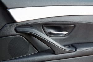 The last step in creating a car stereo system that sounds good is to ensure that the placement of each of the speakers in the vehicle allows for equal and balanced frequency response from both sides of the car. This is crucial to creating a realistic listening experience. With that said, most of us start with a set of
 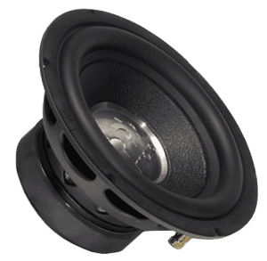 If you want a truly enjoyable and realistic listening environment, consider adding a digital signal processor that allows your installer to fine-tune the output of the left and right speakers at all frequencies so that they sound the same. If your installer knows how to sprinkle in the right amount of time delay so that the output of the right speaker arrives at your ears at the same time as the left, well, chances are you’ll enjoy an impressive soundstage in the vehicle. Your music will be spread evenly from left to right, and with the right recordings, you’ll be able to pick out each instrument or performer and their relative location to one another cross this soundstage.
 We’ve written several articles about
 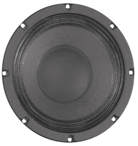 Unfortunately, loudspeakers are notoriously inefficient. A high-efficiency 8-inch midrange driver used in a public address speaker can only transform about 1.3 percent of the power from the amp into acoustic energy. The remainder is converted to heat in the voice coil and, subsequently, the parts around the coil such as the magnet, T-yoke and cone.
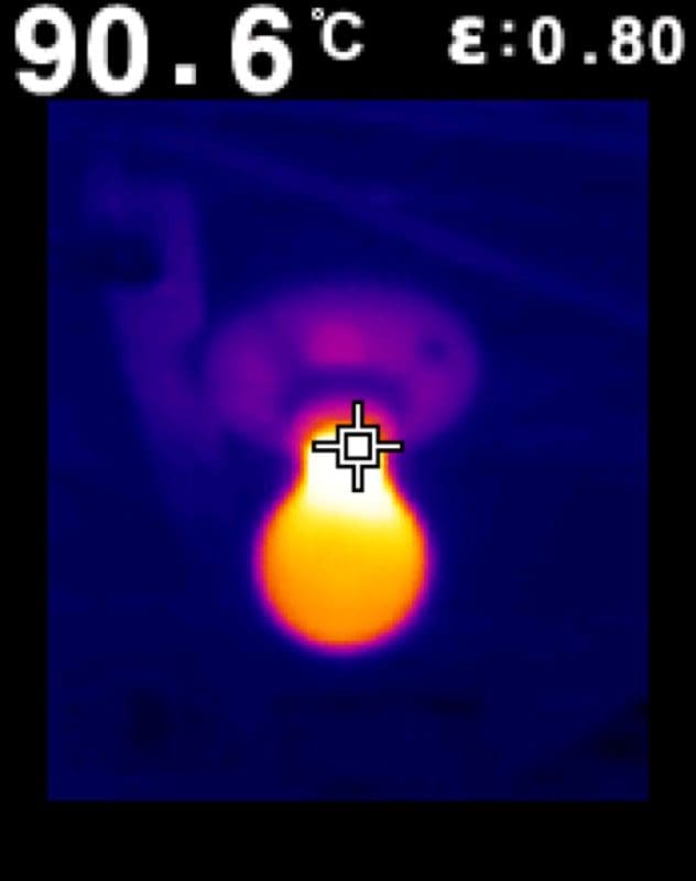
 Heat in a
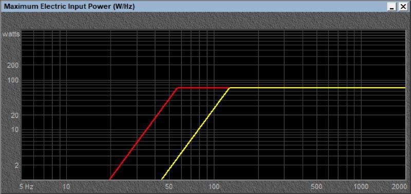
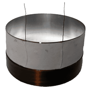
  The ability of any device to handle heat is determined by its size. A 1/8-watt resistor is much smaller than a 1-watt resistor. Generally, the size of a component determines the amount of surface area and the ability to transfer heat into the air. In speakers, the diameter and length of the voice coil winding in a subwoofer are a good indicator of how much heat and, subsequently, how much power the speaker can handle.
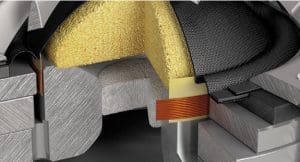 Now, let’s talk about tweeters. Tweeters in
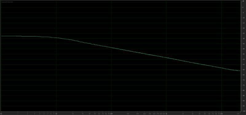
 Depending on the brand, different companies use different processes to test the power handling capabilities of their speakers. It should be noted that some companies have detailed specifications for their testing procedures while others rely simply on data provided by their suppliers, and others guess based on the size of the voice coil used in the design. This is one of the key differences between companies that put significant effort into the design and development of their products and those that pick solutions from a catalog and have their name stamped on the basket and dust cap.