
If you are in your late 40s or older, then you likely grew up with a turntable or tape player in your home as a way of listening to store-bought music. Between 1982 and 1983, the compact disc entered the market and forever changed the way music was stored and transported. In this article, we are going to look at how digital audio works and dispel some of the myths around the conversion between the analog and digital domains.
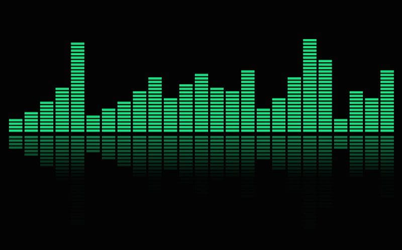
What Is Digital Audio?

In the simplest of terms, a digital audio file is a representation of an analog signal using a series of digital words. In the digital domain, i.e., a computer, information can be stored as a 1 or a 0.
Computers can combine strings of 1s and 0s to represent characters in a text document, colors in a photograph, commands in a program or voltage levels in an audio file.
For decades, the standard for storing audio in the digital domain has been the Red Book Compact Disc Digital Audio (CD-DA) standard of a 44.1kHz sampling rate with a depth of 16 bits.
The sampling rate describes how often a voltage level is measured and stored. To capture the entire audible spectrum of sound, the Nyquist-Shannon sampling theorem states that the sampling rate needs to be at least twice as high as the highest frequency you want to record for it to be recreated with accuracy.
The second consideration in converting an analog signal to the digital domain is the need to store an adequate amount of resolution to properly represent the original signal. The Red Book standard uses a digital word length of 16 bits. This means that there is a string of 16 1’s and 0’s that can be used to represent 65,536 voltage levels. If you are converting the output of a microphone to digital, and the maximum voltage is 1 volt, then a resolution of 16 bits means that the resolution is 0.000015258789 volts. That’s a lot of detail.
Finally, the Red Book standard states that two channels of audio will be sampled simultaneously to create a stereo recording.
Some Quick Math on CD Quality Audio

For those interested, it’s easy to calculate the effective bitrate of a CD-quality audio file. Since we sample the audio signal at 44,100 times a second, and each sample has a voltage level represented by a 16-bit word, and we do this for two channels, 44,100 times 16 times two is 1,411,200, or 1.411 kilobits per second.
To calculate how much space it would take to store a song like “Bohemian Rhapsody” by Queen, you can simply multiply 1,411,200 by the number of seconds in the song (in this case, 355 seconds) for a total of 500,976,000 bits, or about 60 megabytes of data.
How Are Digital Audio Files Created?

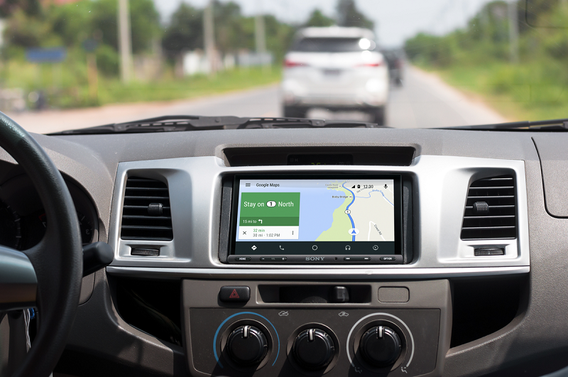
A device called an analog-to-digital converter (ADC) is responsible for taking the analog signal and converting it into a digitally represented value. These devices are commonplace and are found connected to the microphone in your smartphone or the Bluetooth microphone in your car. They are incredibly compact and, relative to when they were first introduced, inexpensive.
ADC work in several ways, but we’ll describe the basics. Imagine, if you will, a series of comparator switches, each stacked one atop the next and referenced to an ever-increasing voltage. We’ll keep the example simple and say that we have eight switches, each of which is triggered at
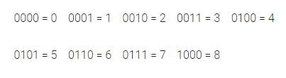
0.125-volt increments. If we feed an analog signal into our comparator switch tree with a level of 0.3 volts, the bottom two switches will turn on, and we get the digital word 0010 (which is 2). If we increase the voltage to 0.8 volts, we trigger all but the last two switches and get the word 0110 (which is 6).
Counting in Digital
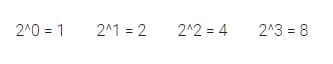
Counting in digital is easy, once you understand how it works. Each space in a digital word represents a value of 2 to the power of the location. So, the first space is 2 to the power of 0, which is 1. The second space is 2 to the power of 1, which is 2, the next space is 2 to the power of 2 which is 4, and so on.
To encode a value using this format, we simply assign a 1 or a 0 to each placeholder such that the sum values represented by the placeholders with a 1 represent the original value.
In our example above, we are using a very low resolution of 3 bits, which means we can show only eight different levels. This limited resolution, of course, introduces some error – known as quantization error. The math can get very complicated very quickly. Suffice it to say that in our example, our theoretical digitizer doesn’t know the difference between a voltage of 0.63 and 0.73 volts. This is a large error and would not work in an attempt to sample audio. Luckily, our 16-bit resolution gives us 65,536 levels from which to choose.
What About Those Crazy Stair-Step Graphs?
You have undoubtedly seen marketing images showing a comparison of CD-quality audio resolution versus high-resolution 96 kHz, 24-bit audio.

While the concept of having a higher sampling rate and more resolution is accurate, it doesn’t mean that the CD-quality audio signal suffers in any way.
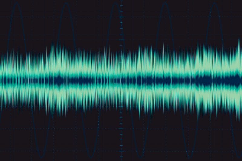
To demonstrate this, we created two 20 kHz test tones in Adobe Audition. The first track has a 96 kHz sampling rate and a resolution of 24 bits.
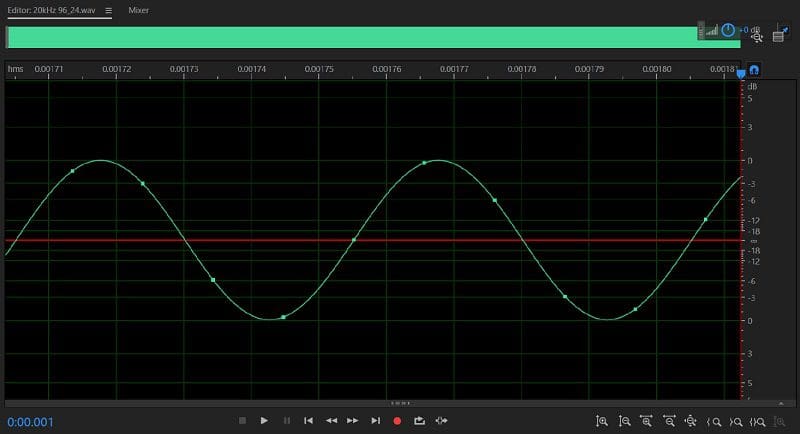
As you can see, the waveform looks smooth and detailed and shows roughly five samples per cycle.
The second track is the same 20 kHz sine wave stored at a sample rate of 44.1 kHz and a resolution of 16 bits.
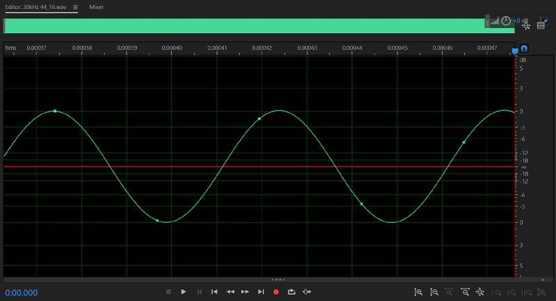
As you can see, there is no significant difference in the shape of the two waveforms. More importantly, they both look like sine waves and neither has any stepping in them.
Understanding Digital Audio
Storing audio signal in the digital domain offers distinct packaging and reliability benefits over analog storage media like vinyl records and magnetic tapes. Of course, digital files don’t degrade over time. Digital files are also impervious to playback speed issues. If your turntable or cassette deck is playing too slowly, the music won’t sound right.
In a future article, we’ll look at the file format options available for storing digital audio files. Until then, be sure to drop by your local specialist mobile enhancement retailer to see all the latest digital media-compatible source unit upgrades available for your car, truck or SUV.
This article is written and produced by the team at www.BestCarAudio.com. Reproduction or use of any kind is prohibited without the express written permission of 1sixty8 media.


 As the next topic in our series explaining amplifier specifications, we will look at the frequency response information that manufacturers provide and explain how to interpret this information. In the simplest of statements, the frequency response spec will tell you about the low- and high-frequency limits of the amplifier based on its design. As with all the specs we have looked at, the information provided is as telling as the information that may be missing from the spec page. Let’s dive in and have a look.
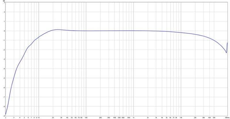
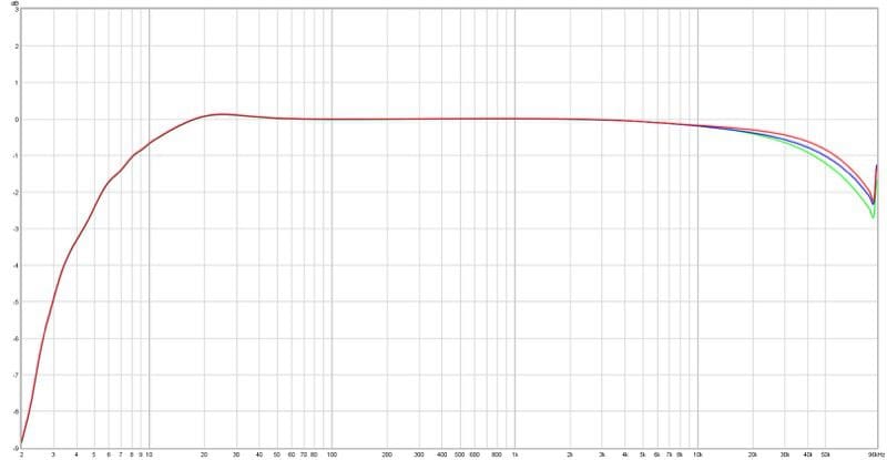
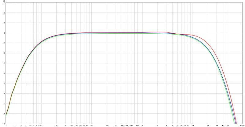
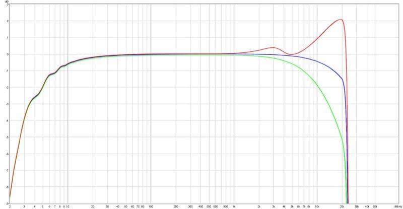
 For most applications, you can ignore the frequency response measurements of the amplifiers you choose. The majority will be adequately flat from 20 Hz to 20 kHz. If you plan on driving a low-impedance load (low-impedance drivers or many drivers wired in parallel), the added impedance will dramatically reduce the high-frequency performance of a Class-D amp.