
These days, it seems like there are more vehicle technology options than ever that can plug into the power outlet in your car or stick to the windshield. The problem with using the cigarette lighter outlet in your vehicle is that you end up with a lot of wire clutter and components attached to your windshield that can obstruct your vision and be very distracting. In this article, we are going to talk about keeping the interior of your car looking original while still adding great technology that will make your drive more efficient, entertaining and safe.
GPS Portable Navigation Systems
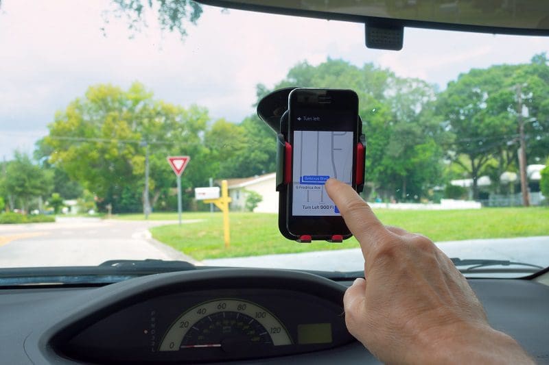
Everyone has seen a driver with a Garmin, TomTom or Magellan navigation system stuck to their windshield. While these devices are a great way to make traveling safer and more efficient, they are one of the biggest and most obtrusive additions you can make to your field of vision. Yes, having navigation information with voice prompts can reduce the potential for sudden, last-minute lane changes, and they are certainly better than having to look at a paper map while driving. On the downside, a bright display right in front of you can reduce your long-distance vision at night, and the constant stream of information is distracting.
A great solution is to install a new multimedia receiver that includes built-in GPS-based navigation. Modern receivers replace the radio in your car and provide a fully integrated solution that knows when to adjust the radio volume to let you know well ahead of time what lane to be in and when to make a maneuver. If the voice prompts aren’t enough, the screen is still available to give you additional information while staying out of your line of sight.
Smart Phone Mounts and Brackets
Pretty much every smartphone has access to a navigation application like Google Maps or Waze. These programs and the associated access to the internet for real-time traffic flow information offer a dramatic improvement in accuracy and efficiency over a portable navigation system. Voice recognition systems like Google Assistant and Apple’s Siri help you plan a route without having to touch the screen. The downside to using your phone is that you need to plug it in and place it somewhere that’s easy to see. Windshield, console, air vent and cup holder brackets are convenient but add clutter and wires running around the car interior.
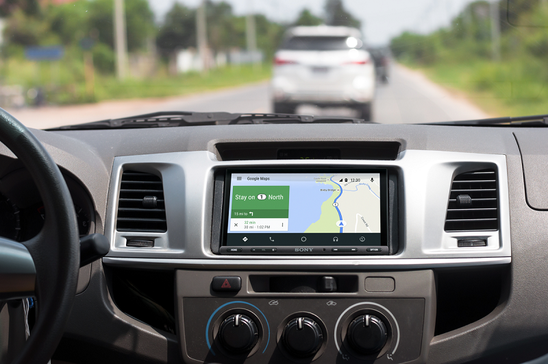
A truly elegant solution is to choose a multimedia receiver with Apple CarPlay and Android Auto built into it. Not only can you get turn-by-turn directions, but you can also make phone calls, send text messages and choose from at least a dozen music or streaming audio services to keep you entertained.
Many of the latest multimedia receivers include wireless connectivity for Apple CarPlay and Android Auto. If you choose one of these solutions, you can keep your phone in pocket or purse while still being able to communicate as you’ driving down the road.
Phone Chargers
It seems like everyone has purchased at least one USB charging plug at one time or another. They are handy for topping up the battery in your phone while you drive and, in most cases, provide more current than the USB port built into the factory entertainment system. The downside, again, is clutter. Cables wear out and you still need somewhere to store your phone while you drive.
Many of the latest smartphones from Samsung and Apple support Qi (pronounced “chee”) wireless charging. Your local mobile enhancement retailer can source and install a vehicle-specific or custom wireless charging base in your vehicle. Once it’s integrated into your car or truck, all you have to do is place your phone in your center console, armrest or glovebox and the high-strength neodymium magnets in the Qi system will hold it in place while it charges wirelessly.
Another option is to ask your local mobile enhancement retailer to add a high-current USB port to your glovebox or center console so you can charge the phone while keeping it safe and secure.
Custom-Installed Radar Detectors

If you are a driving enthusiast or want to avoid the wasted time and money associated with speeding tickets, then you have likely considered, or already own a radar detector. The most cost-effective options are portable units that stick to your windshield or rearview mirror. While these solutions offer good radar performance, they can be a visual distraction and don’t offer protection from police laser systems.
If you want to beat police lidar, then a custom-installed radar system from Escort, K40, Radenso or Stinger is your only choice. These systems include laser transmitters that send a scrambled signal as soon as they detect that a lidar gun is being used. This scrambled signal prevents the police officer from taking a reading until you slow to a legal speed and cancel the transmission. Once canceled, the officer can try again, see that you are close enough to the speed limit and let you carry on your way. Of course, custom-installed radar detectors stay out of your line of sight, with no cables or wires visible in your vehicle.
As we’ve established throughout this article, it should be no surprise that a custom-installed radar detector and laser defense system will be practically invisible in your vehicle. Some detectors use a tiny control panel that’s about the size of a stick of gum while others use a wireless remote to enable you to operate the system. In most cases, a hidden speaker provides voice prompts to warn you about police activity.
SiriusXM Satellite Radio
If you travel a lot or live in a rural area, then finding music you enjoy on a radio station can be tricky. Adding satellite radio to your car or truck is a perfect solution, but using a solution like the Onyx or Stratus adds clutter and a “tacked on” look to your dash. Dozens of aftermarket radios are available from such companies as Sony, Alpine, Kenwood, JVC and Pioneer that offer integrated satellite radio solutions. Once installed, these radios blend nicely with your vehicle interior and in most cases, you can change stations using the steering wheel stereo controls that came with your vehicle.
Backup Camera Systems
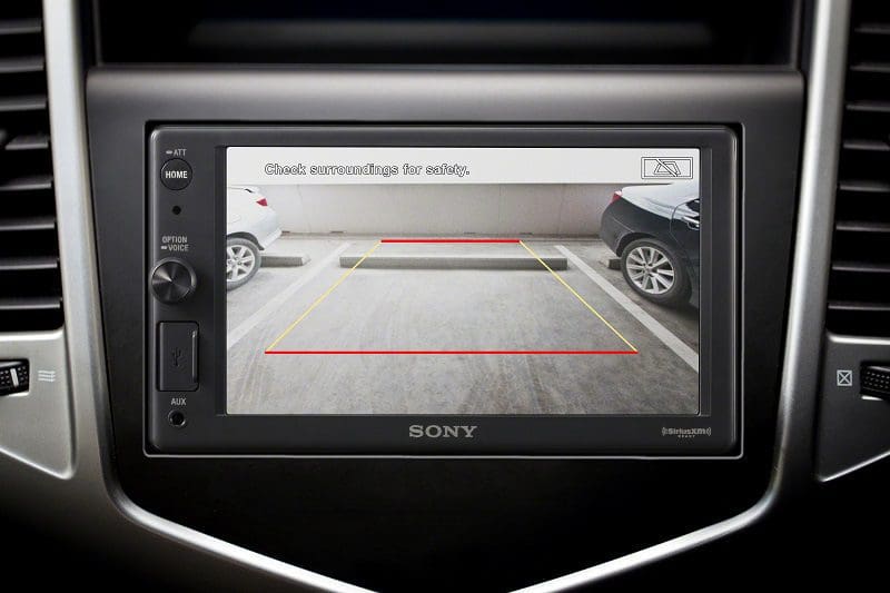
Many big-box and auto parts stores offer backup camera systems that include a stand-alone monitor to display an image of what is behind your vehicle. While having a backup camera is one of the best safety systems you can add, having even a small display on your dash or console takes away from the tidiness of your vehicle interior.
Your local car audio specialist retailer has many options for adding a backup camera to your vehicle while making it look as though it belongs. In some cases, the image from the camera can be displayed on the factory-installed color screen in your dash. If you don’t have a screen, a variety of aftermarket rearview mirrors with built-in LCD displays will show what’s behind your vehicle. If you have upgraded to a new multimedia receiver, that screen is also an option.
Seat Heaters
In the northern U.S. and across Canada, commuters dread getting into their cars on a cold winter morning and sitting down on a seat that’s essentially frozen. Heating pads that plug into your power outlet offer some help, but even the best look like the afterthought that they are.
Original equipment-style heating elements can be installed under the cloth, vinyl or leather upholstery in most vehicles. If you have a remote car starter, your seats can be nice and warm when you get to the vehicle or, at the very least, will warm up quickly once you start the car.
Visit Your Local Specialist Mobile Electronics Retailer Today
If you are interested in adding a feature or technology to your car, truck or SUV, drop by your local specialist car stereo shop today and ask them about options for integrating that technology into your vehicle.
This article is written and produced by the team at www.BestCarAudio.com. Reproduction or use of any kind is prohibited without the express written permission of 1sixty8 media.
 As the next topic in our series explaining amplifier specifications, we will look at the frequency response information that manufacturers provide and explain how to interpret this information. In the simplest of statements, the frequency response spec will tell you about the low- and high-frequency limits of the amplifier based on its design. As with all the specs we have looked at, the information provided is as telling as the information that may be missing from the spec page. Let’s dive in and have a look.
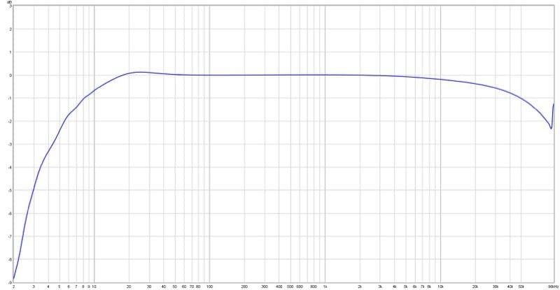
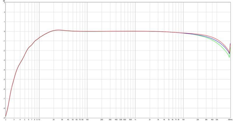
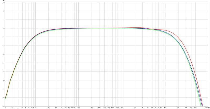
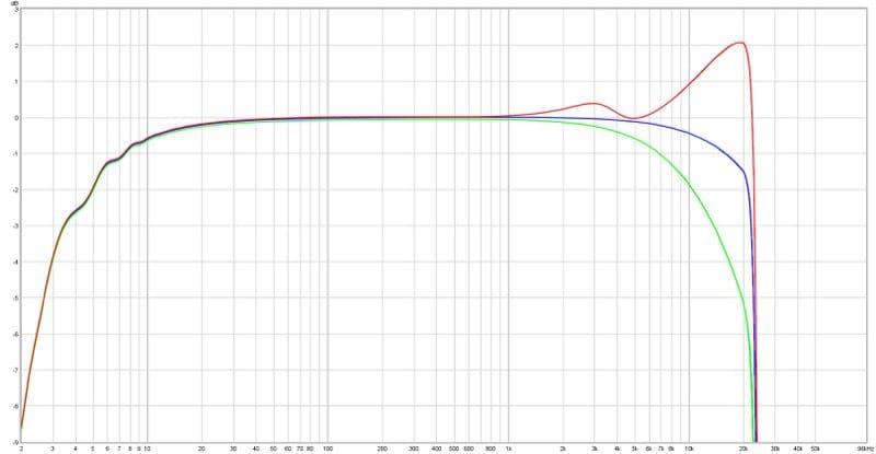
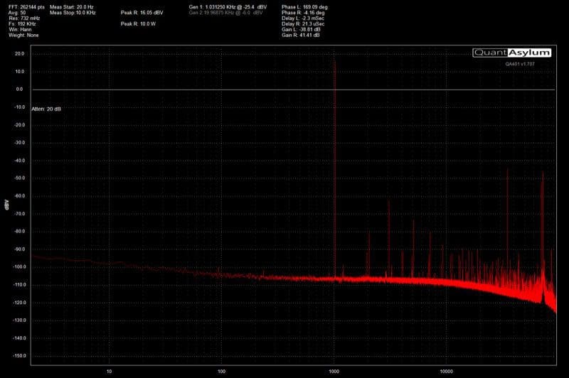
 For most applications, you can ignore the frequency response measurements of the amplifiers you choose. The majority will be adequately flat from 20 Hz to 20 kHz. If you plan on driving a low-impedance load (low-impedance drivers or many drivers wired in parallel), the added impedance will dramatically reduce the high-frequency performance of a Class-D amp.
 The next topic in our look at
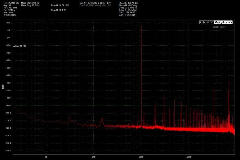
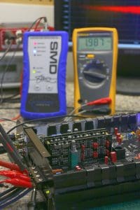 Being able to get full power from your amplifier from a variety of signal sources is important to ensuring that your installer can make that amp work with any source. If you have a high-quality aftermarket source unit, the preamp outputs should provide 2 or 4 Vrms of signal with the volume at maximum and a recording at 0 dB.
 When it comes to having a fully active audio system installed in your vehicle, unless you choose to implement a stand-alone
 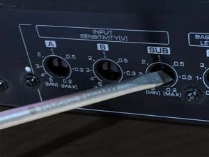 If you have understood this article fully, then you realize that more signal from your
  Welcome to our new series about understanding product specifications. Our goal in these articles is to help you understand what the
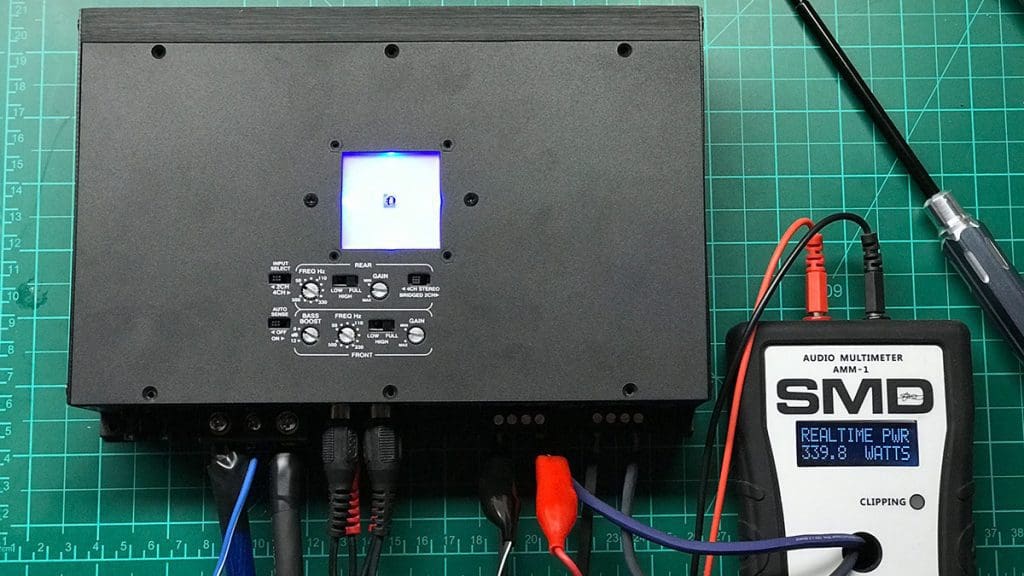
  Without a doubt, the most popular specification that consumers look at when purchasing a car audio amplifier is its power rating. An amplifier takes the small signal from your source unit and increases it in voltage and current to drive a low-impedance speaker. In a nutshell, the more power you have, the more loudly you can play your car stereo system before the signal going to the speakers distorts. The limit of how much power is required is determined by the power handling specifications of the speakers in the vehicle, their cone excursion limits and their
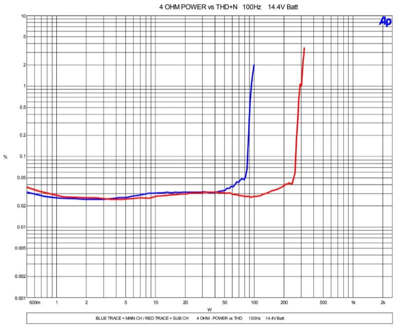
 In layman’s terms, the amp must perform as well producing bass as it does high-frequency information, and the specified power rating cannot include large amounts of distortion. While the 14.4V rating is somewhat high, it establishes a level playing field from which consumers can compare results.
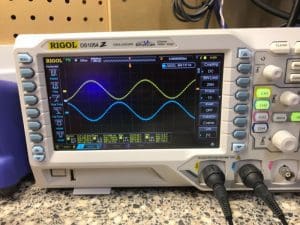 If you don’t see the CTA-2006 logo associated with a product you are considering, there are several ways that the numbers may not be directly comparable with other options. One easy way to inflate numbers is to increase the supply voltage to the amp. Depending on the design of an amplifier’s power supply, each additional volt provided to that power supply could theoretically increase the amplifier’s output by about 0.6 dB. That would be like a 100-watt amp being able to make about 115 watts.
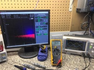 If you are shopping for an amplifier, the power rating does nothing to tell you about the quality of one amplifier compared to another. You don’t need 100 watts to drive your tweeters and you certainly won’t be happy with a 25-watt amp driving a subwoofer in your car.