 If you are an avid car audio enthusiast, it’s likely that you’ve seen photos of or heard systems that use high-efficiency pro audio style speakers. These drivers were designed for PA systems at concerts and can produce impressive output levels with moderate levels of power from an amp. In this article, we are going to look at the benefits and drawbacks of using pro-sound speakers in applications like a motorcycle.
What Determines Speaker Efficiency?
 Before we dive into the differences between conventional car audio speakers and high-efficiency speakers, let’s take a quick look at the definition of speaker efficiency and what design features change this value.
Speaker efficiency specifications describe how much acoustic output a speaker produces for a given amount of input signal. A proper rating will look something like this: 88 dB (2.83 V/1M). This specification means that the speaker will produce a sound pressure level of 88 dB when driven with 2.83 volts of signal from an amplifier and measured using a microphone placed 1 meter away from the face of the speaker cone. Increasing or decreasing the supplied power will dramatically affect the specification. As an example, you may see companies use the 1 watt/1 meter standard. 2.83 volts is 1 watt of power into an 8-ohm load. For a 4-ohm car audio speaker, 2.83 volts is 2 watts. You can subtract 3 dB from the 2-watt specification to get the 1-watt number, and vice-versa.
 Several technical design details determine speaker efficiency. One of the biggest factors is the weight of the cone and voice coil assembly. A lightweight cone assembly is easier to move and typically produces more output with less power. The drawback of this low-mass design is that the resonant frequency of the speaker will be higher and the driver won’t produce anywhere as much bass. This is the basic trade-off between conventional car audio speakers and pro-sound drivers.
Efficiency Versus Low-Frequency Output
When reproducing music, extended low-frequency extension adds a great deal of impact and realism to the listening experience. Vocals and midrange from the 175 to 200 Hz region are of course crucial, but adding another octave below that is the difference in between listening to music from a smartphone or a clock radio and the capabilities of a real stereo system.
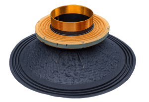
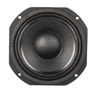
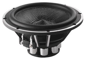 Let’s compare two popular 6.5-inch woofers, both intended for car audio applications. Speaker A is a conventional car audio woofer designed to be used with a tweeter and is intended for installation in the door of your car or truck. Speaker B is a high-efficiency pro audio style midrange and will also need a separate tweeter to play above 3,000 Hz.
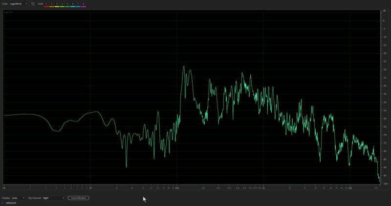
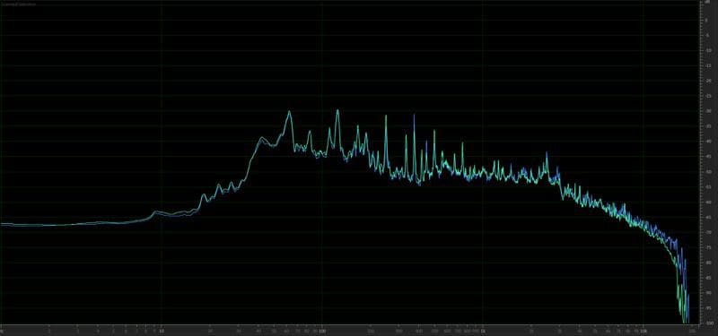
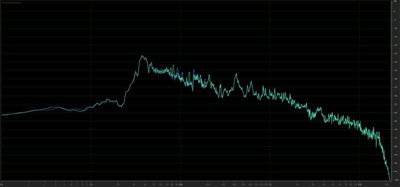
The graph below shows the predicted low-frequency response of Speaker A in red and Speaker B in yellow in an effectively infinite baffle application (a door or motorcycle fairing that isn’t sealed). The shown levels refer to each driver being supplied with 1 watt of power.
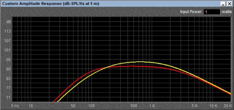
As you can see, Speaker A produces about 90.5 dB of output at 630 Hz where Speaker B is at 93.3 dB. The trade-off is that Speaker B only produces 81.4 dB of output at 70 Hz where Speaker A produces 84 dB. These numbers are actually pretty small, but the overall tonal balance of the two options would be audible.
If you look at some of the popular target equalization curves that tuners use, they typically tune for flat midrange response from about 3,000 Hz down to around 100 Hz. Emphasis in the upper midrange is not typically desirable. If you have a digital signal processor in your system, your tuner could use the equalizer to lower those frequencies, but that doesn’t make the bass region play any louder in absolute terms.
How Loudly Will It Play?
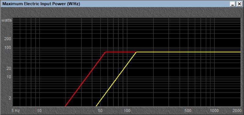
When it comes to motorcycle audio, clients want their systems to play as loudly as possible to drown out loud exhaust systems and wind noise while on the freeway. The defining factor in how loudly a speaker will play is its excursion capability. For our example above, Speaker A is rated to have an Xmax specification (one-way excursion limit) of 4 mm while Speaker B is limited to 1.2 mm because of its short, lightweight voice coil former.
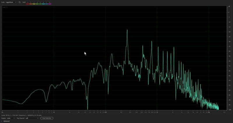
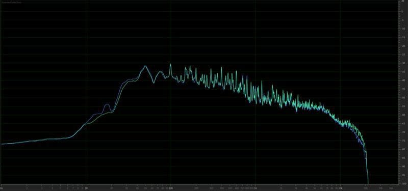
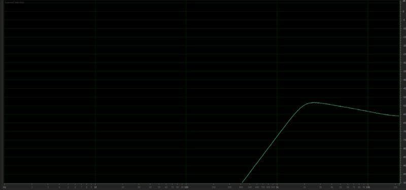
The graph below shows how low each driver can play when driven with 70 watts of power before the cone assembly starts to leave the magnetic gap and distortion increases dramatically. With the high-efficiency pro audio speaker, you will have to implement a high-pass filter in the system to limit power below 150 Hz. With Speaker A, you can let the driver play down to 60 Hz before the voice coil starts to come out of the gap with the same amount of power.
Which Speaker Solution Is Right for Your Application?
Based on the science behind how speakers work, the argument for using a pro audio type speaker without the addition of a dedicated woofer of some sort seems illogical. If the amount of power you have available is limited, then a high-efficiency speaker might be worthwhile. With that said, even the smallest of high-quality amplifiers can produce at least 45 or 50 watts of power, which should be more than enough to drown out road and wind noise in almost any situation.
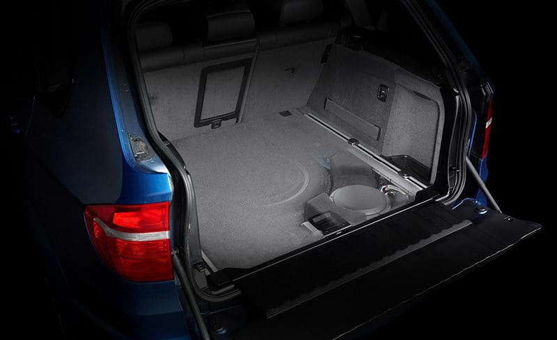
 If you have plans to add a dedicated woofer to the saddlebag or trunk on your bike, and can find one that will play up to 150 or 200 Hz without significant distorting, then pro-style high-efficiency speakers may be a good option if all that matters is how loudly the system will play.
It’s worth noting: If you look at motorcycle and powersports-specific upgrade packages from companies like ARC Audio, Rockford Fosgate, JL Audio and Kicker, they all use a conventional speaker design that offers great bass performance.
If you need a hand choosing the right speaker for your application, drop by your local specialist car stereo retailer. They can provide some insight into the best solution for your vehicle and your listening style.
This article is written and produced by the team at www.BestCarAudio.com. Reproduction or use of any kind is prohibited without the express written permission of 1sixty8 media.
 Did you know that in Europe, there aren’t nearly the number of qualified
 When you say the word subwoofer to someone, they often envision someone driving down the street with a wall of woofers, shaking windows and being otherwise annoying. The reality is, adding a subwoofer to even a premium
 Understanding how to recreate
  At the most fundamental level, sounds are vibrations that travel through air and other mediums. These vibrations are detected by our ears, which in turn convert them to minute electrical signals that our brains interpret.
 To achieve this goal, you need at least a two-way speaker system. Because no single speaker can reproduce the entire audio spectrum (from deep bass to the highest highs) with good efficiency and dispersion, we dedicate different size drivers to different frequency ranges. In the simplest of systems, you’d have woofers (not to be confused with subwoofers) that play frequencies below about 3,000 Hz. For the top end, you’ll need tweeters to cover the frequencies above 3,000 Hz.
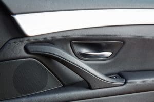 The last step in creating a car stereo system that sounds good is to ensure that the placement of each of the speakers in the vehicle allows for equal and balanced frequency response from both sides of the car. This is crucial to creating a realistic listening experience. With that said, most of us start with a set of
 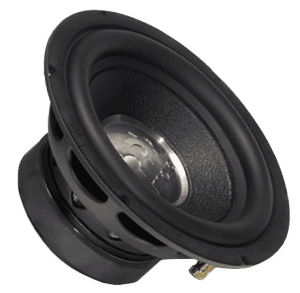 If you want a truly enjoyable and realistic listening environment, consider adding a digital signal processor that allows your installer to fine-tune the output of the left and right speakers at all frequencies so that they sound the same. If your installer knows how to sprinkle in the right amount of time delay so that the output of the right speaker arrives at your ears at the same time as the left, well, chances are you’ll enjoy an impressive soundstage in the vehicle. Your music will be spread evenly from left to right, and with the right recordings, you’ll be able to pick out each instrument or performer and their relative location to one another cross this soundstage.
 We’ve written several articles about
 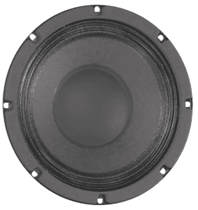 Unfortunately, loudspeakers are notoriously inefficient. A high-efficiency 8-inch midrange driver used in a public address speaker can only transform about 1.3 percent of the power from the amp into acoustic energy. The remainder is converted to heat in the voice coil and, subsequently, the parts around the coil such as the magnet, T-yoke and cone.
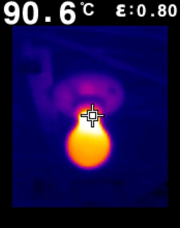
 Heat in a
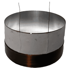
  The ability of any device to handle heat is determined by its size. A 1/8-watt resistor is much smaller than a 1-watt resistor. Generally, the size of a component determines the amount of surface area and the ability to transfer heat into the air. In speakers, the diameter and length of the voice coil winding in a subwoofer are a good indicator of how much heat and, subsequently, how much power the speaker can handle.
 Now, let’s talk about tweeters. Tweeters in
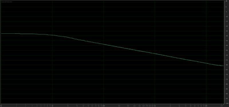
 Depending on the brand, different companies use different processes to test the power handling capabilities of their speakers. It should be noted that some companies have detailed specifications for their testing procedures while others rely simply on data provided by their suppliers, and others guess based on the size of the voice coil used in the design. This is one of the key differences between companies that put significant effort into the design and development of their products and those that pick solutions from a catalog and have their name stamped on the basket and dust cap.
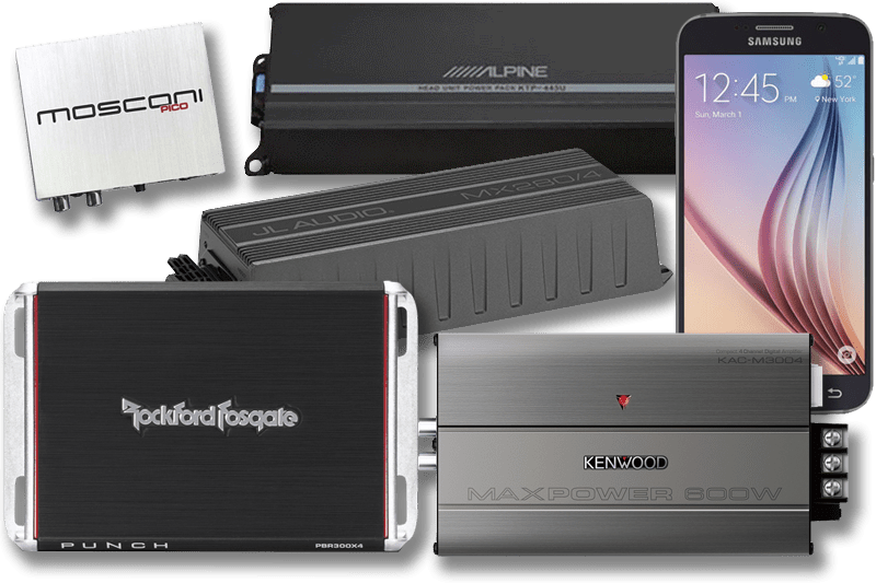 It’s hard not to notice that almost every reputable
 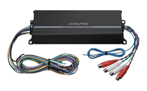 One of the first modern high-power compact amplifiers to make its mark in the industry was the Alpine Power Pack KTP-455U. Measuring roughly 8 by 2.5 by 1.5 inches in size, this four-channel amplifier could deliver a real-world 45 watts per channel into 4-ohm loads. Alpine marketed this amplifier as an easily integrated solution to upgrade a factory or aftermarket radio and deliver almost three times as much power to your speakers.
 A few years later, Rockford Fosgate introduced its Boosted Rail Technology series of