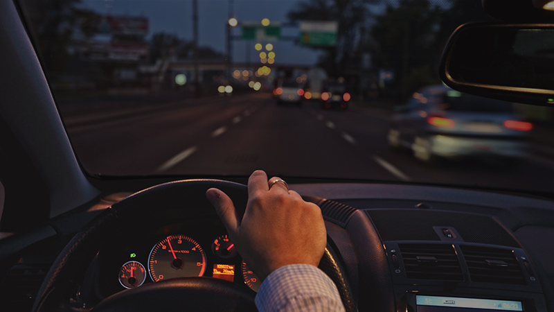
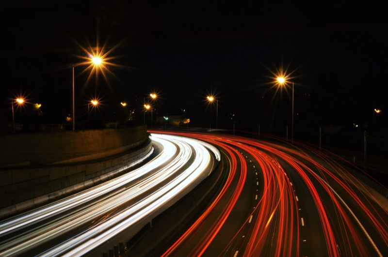
 Your lighting system remains the most important safety component of your vehicle once the sun sets. If you can’t see objects around you, or far enough ahead of you, the chances of having a serious accident are significant and the outcome could be deadly. Ensuring proper night vision is the most important aspect of driving after sunset. Follow along as we learn about lighting and explore some nighttime driving tips.
Headlight Components and Modifications
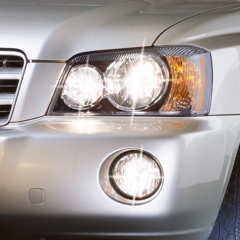 There are many options for improving how far you can see at night. Upgraded headlight bulbs and new headlight assemblies are the most popular. If you are fanatical about your lighting, you may want to look into a headlight retrofit. The retrofit process involves taking the headlight assembly apart and installing new projectors, and often new HID bulbs and ballasts.
When it comes to light assembly upgrades, too many times, people choose something that looks good or adds a little style to their vehicle. Halo rings and LED strips look cool, but don’t forget to focus on sheer performance. A proper beam pattern and efficient light production are what keep you safe.
Auxiliary Lighting Upgrades
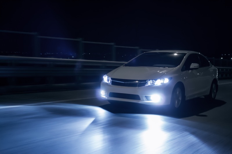 Choosing a set of auxiliary lights is a great way to increase the distance you can see. Many companies offer high-quality LED lights that your mobile enhancement retailer can integrate into your vehicle.
Be careful, though – not all lighting is legal to use on public roads. Those cool 54-inch curved LED light bars are amazing when you decide to head out on the trails after dark, but they may not be legal for use around town. Check the laws in your area before you purchase. If you want to be sure your upgrade is legal, look for DOT or SAE approval on the light assembly. When installed properly, these lighting systems won’t blind oncoming drivers.
Eight Tips to Improve Night Vision while Driving
Let’s face it: The only time we need our lighting system is after the sun sets. Upgrading bulbs, lenses and light assemblies go a long way to ensuring we are safe. There are several other things you can do to ensure you can see as far as possible. Here are eight things you can do to improve your night vision. Most of them are completely free!
1 – Make sure your lights are perfectly aimed
If you get flashed by oncoming drivers, see the leaves in the trees above your car or can’t see very far, the first step is to ensure your lights are aimed properly. Seek out the expertise of a local mobile enhancement retailer that specializes in lighting upgrades for help with the alignment process.
2 – Turn down the dash lights
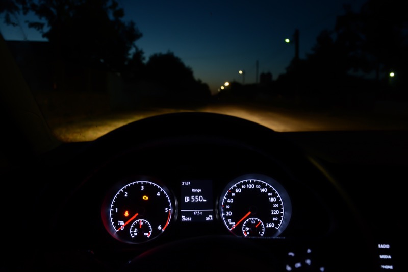 When the lights on your dash are bright, the irises of your eyes will contract to reduce the amount of light that enters them. While this works great for balancing the brightness of lighting in the vehicle, it can work against your ability to see for long distances. If you keep the interior dark, you can see farther.
3 – Turn off your fog lights
Your fog lights cause a situation similar to overly bright dash lighting. If the area directly in front of your vehicle is bright, your eyes will adjust to that light level and reduce how far you can see. A properly designed lighting system should provide balanced foreground and long-distance light.
4 – Keep those lenses in good shape
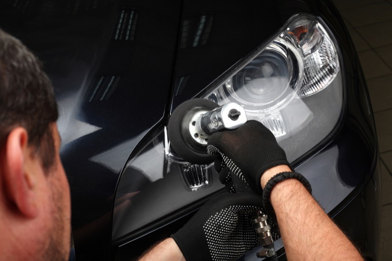 If the plastic lenses on your headlights are yellowing or chalky, they will reduce the amount of light that gets from the bulb to the road. Many high-quality lens restoration kits are available that can restore lens clarity and improve visibility.
5 – Keep your windshield clean
It only makes sense that being able to see out of your vehicle is going to improve your ability to drive safely at night. Use a high-quality glass cleaner and a lint-free cloth or microfiber towel to keep the interior of the windshield clean. A great trick for getting rid of stubborn, oily film that builds up over time is to use newspaper and your favorite window cleaner to wipe the windows. The newspaper won’t leave any lint.
Keep the outside of your windshield clean as well. If a cloth or cleaner won’t remove everything, you can escalate to a clay bar or even 0000 steel wool. Just keep the steel wool away from the trim.
6 – Be careful where you look
 When a car is coming toward you, try not to look into the light. In the same way that bright dash lights cause your irises to close, so too will oncoming headlights. Some advanced driver training courses even suggest closing one eye. We suggest trying to focus ahead of your vehicle.
7 – Be prepared for rain
Few things are worse than trying to drive at night while it’s raining. Ensure your wiper blades are in excellent condition and aren’t leaving streaks. If they are, you can try cleaning the edges with a little isopropyl alcohol and a soft cloth. The next step is to simply replace your wiper blades – they don’t last forever.
Treating your windshield with a high-quality hydrophobic window treatment like Aquapel, Opti-Glass or Rain-X will help water bead up and roll off your windows without your having to use your wiper blades at all.
8 – Take care of your eyes
 Eat your carrots! OK, well, eat whatever you want, but don’t look at the sun or a solar eclipse. Make sure you wear high-quality sunglasses to prevent macular degeneration from UV exposure. Wear “computer glasses” if you are going to be staring at a monitor all day. If you are working with power tools or in risky situations, wear safety glasses or goggles. Most importantly, visit an optometrist regularly to stay on top of your eye health.
Drive Safely
Combining the above tips with a properly aimed, high-quality lighting system can dramatically increase your safety, and the safety of those around you. If you are interested in upgrading your lighting system or adding more lights, drop by your local mobile enhancement retailer and talk to them about your needs.
This article is written and produced by the team at www.BestCarAudio.com. Reproduction or use of any kind is prohibited without the express written permission of 1sixty8 media.