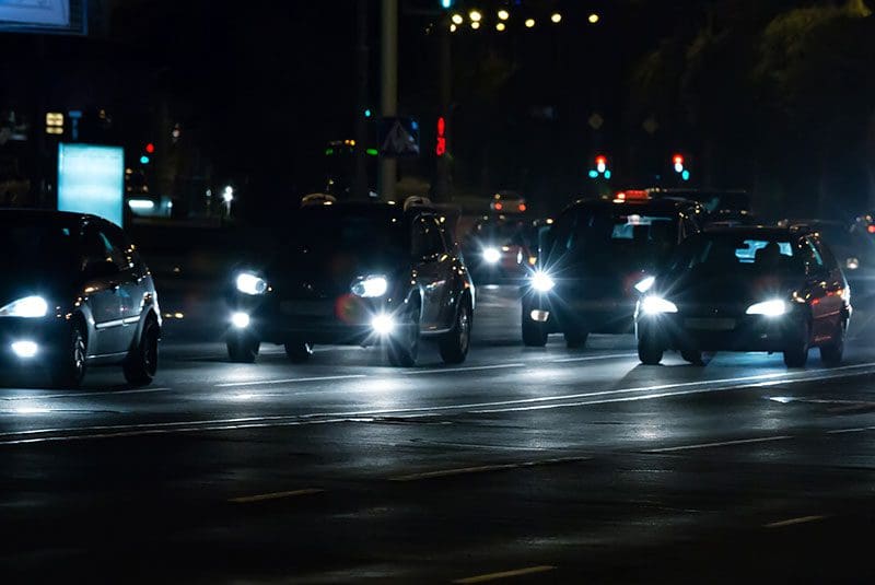
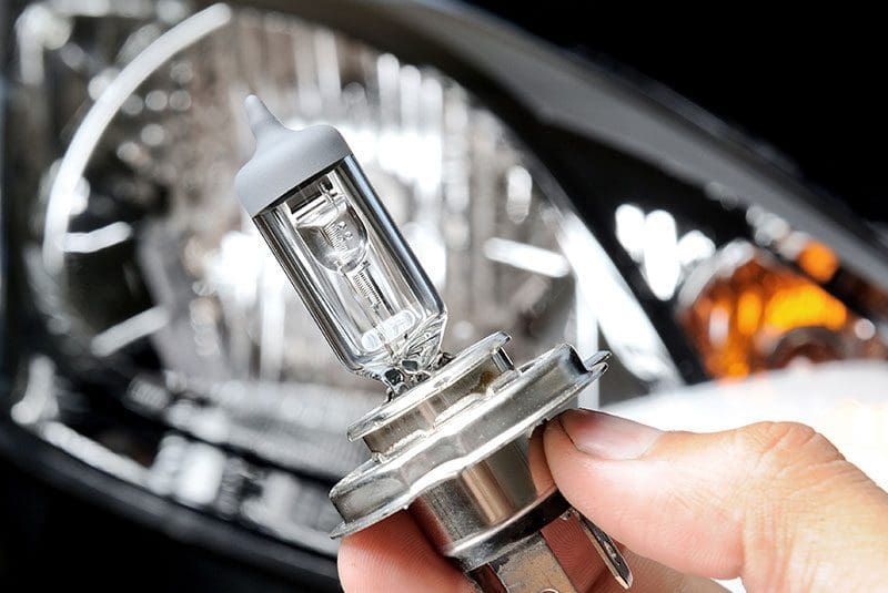
Upgrading the headlight bulbs in your car or truck can dramatically improve your safety and the safety of other drivers, pedestrians and cyclists. Your local mobile enhancement retailer may offer high-quality HID or LED bulb upgrade kits in a variety of color temperature options. These colors typically vary from 3,000 to 12,000 K. The question is, what do these color ratings mean and how do the numbers affect useful light output and style? Keep reading to find out.
What Does Headlight Bulb Color Temperature Mean?
 Bulb color temperature, or more accurately, correlated color temperature describes the spectrum of energy released by a light bulb and is rated in kelvins. In the simplest of terms, color temperature is related to the physical temperature of the light source, and correlated color temperature is an equivalent spectral description for HID and LED bulbs.
Let’s consider a standard incandescent light bulb as an example. When a small amount of voltage is applied, the filament will glow with a dull red appearance. When supplied with its full rated voltage, the filament temperature increases and the energy output is whiter. The same happens as you heat a metal like steel. It glows red, then orange, yellow and white as you increase its physical temperature.
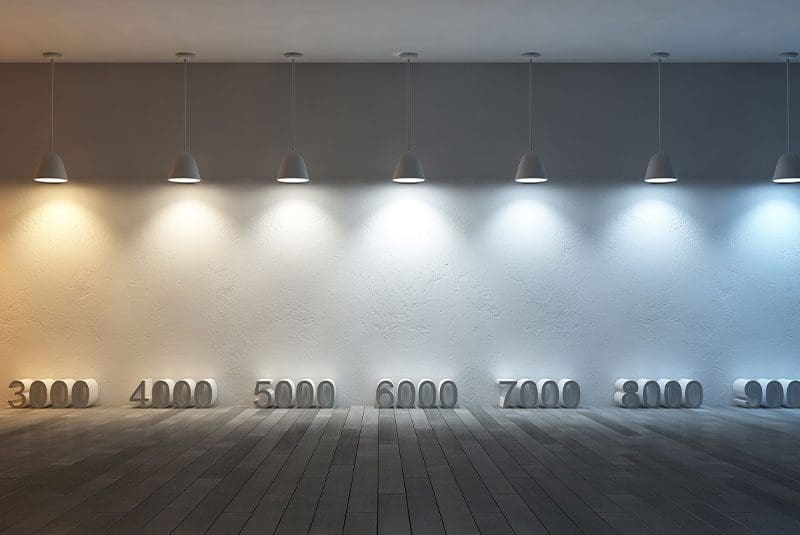
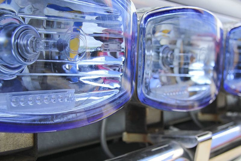
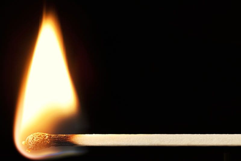 To give you an idea of how color temperature numbers work, a match flame has a color temp of approximately 1700 K, a standard residential incandescent lamp is around 2400 K, cool white fluorescent lamps are around 5000 K, and vertical daylight (when the sun is directly above you) is around 5700 K. Calculating color temperature gets complicated quickly and in most cases, the labels on the packaging of the bulbs you choose are rough estimates that give you an idea of whether the bulbs are on the yellow (3500 K), white (6000 K) or blue (9000 K) ends of the spectrum.
Headlight Bulb Light Output
 The standard measurement for light output is the lux or lumen. The term lux describes how much illumination is produced by a light source at a given distance. It stands to reason that any lux rating should include a distance at which the measurement was taken. If you are browsing a LED light bar website, you will often see lux ratings taken at a distance of 10 meters. The often-misused term lumen describes the total light available from a light source. In most cases, these measurements need to be performed in laboratory conditions and more importantly, for consumers, the information typically applies to a bulb design, rather than the effective illumination ability down the road.
Color Temperature versus Light Output
 Is there a direct correlation between the color of light that a bulb assembly produces and how much usable light is put on the road? When aftermarket HID kits started to gain popularity, light output was inversely proportional to color temperature. This relationship means that a yellowish to white bulb produces more light than a white to bluish bulb. The reality is that there are so many variables among bulb designs and suppliers that an accurate comparison is nearly impossible. That said, here is a real-world example we found on one headlight retrofitter supply website:
| Color Temperature | Description | Bulb Output |
| 4500 K | Warm White | ~3500 lumens |
| 5500 K | Pure White | ~3400 lumens |
| 6500 K | Cool White | ~3200 lumens |
What Headlight Bulb Color Is Best?
 Our eyes react very differently to different light colors. Blue to purple light has shorter wavelengths than orange and yellow light and can cause eye fatigue. If you wear glasses, you may have seen “computer user” coatings with a brownish tint. This brown tint reduces how much blue light is passed and can ease eye strain.
Most factory-installed lighting systems use bulbs with a color temperature in the 5000 to 5500 K range. This temperature strikes an excellent balance between light output and appearance. The bulbs look MUCH whiter than any clear halogen design.
As a note, certain jurisdictions have very specific laws about headlight colors. Be sure to find out what is legal in your area before choosing something that varies too far from pure white.
Upgrade Your Headlights for Improved Safety
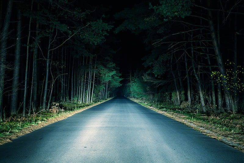
Ensuring that you can see safely down the road is crucial to your safety while driving. Upgrading your headlights with new bulbs is an easy and relatively inexpensive way to increase the distance you can see ahead of you. Your local mobile enhancement retailer can help you choose an LED or HID upgrade solution and color that will offer added performance and cool looks!
This article is written and produced by the team at www.BestCarAudio.com. Reproduction or use of any kind is prohibited without the express written permission of 1sixty8 media.