To close out our series of educational articles on amplifier specifications, we are going to talk about operating voltage limits and, by association, the protection circuits built into a car audio amplifier. In the good old days of electrical systems that were composed of an alternator, battery, switches and a couple of relays, delivering a relatively constant voltage to a car audio amplifier was easy. New technologies and limits on battery, alternator and wire size have made it much more difficult to keep our amplifiers happy.
Automotive Start-Stop Systems Cause Low Operating Voltage
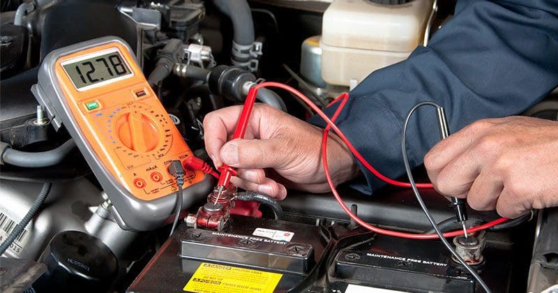
 With the never-ending battle to eke out every ounce of fuel efficiency from the vehicles we drive, automakers have resorted to systems that will shut down the engine to save fuel while idling. Transitioning from standard idle mode to the shut-down state doesn’t pose a problem for most amplifiers as the battery voltage only drops to the 12.2 to 11.5-volt range. If the voltage starts to drop because the car has been idling too long, the engine will restart automatically.
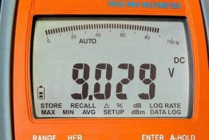 What poses a problem for modern car audio amplifiers are the voltage dips associated with the engine starting. In conventional vehicles, the stereo is off while you are starting the vehicle. These start-stop systems keep everything running and playing as the engine restarts. Electrical system voltage can drop below seven volts while the engine cranks. Many amplifiers shut themselves down below nine or ten volts, and as such, your music would stop playing. While a pause in your music isn’t truly problematic, it can be annoying if you are stuck in stop-and-go traffic.
New amplifier designs include circuitry that will keep the amplifier active during brief low operating voltage conditions. Some companies specify their amps as being able to handle as little as 6 volts for as long as 5 seconds to ensure that your music plays without interruption. This same start-stop compliance design is required for digital signal processors to prevent them from shutting down during engine restarts.
Car Audio Amplifier Protection Circuitry
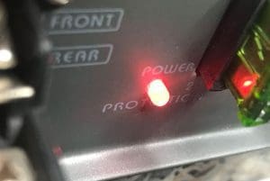 Three decades ago, if you shorted the outputs of an amplifier, it would blow up, occasionally with spectacular results. Modern amplifiers include protection circuits that monitor different functions and automatically shut the amp down when an unwanted condition occurs. Most amplifiers include protection against overheating or short circuits on the speaker wires. Better amplifiers may provide a warning if a power connection over-voltage condition occurs that could damage the components inside the amp.
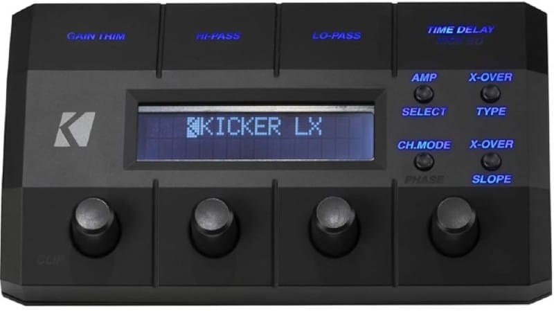
A select few manufacturers provide computerized monitoring of different parts of their amplifiers and flash error codes to let users know why the amp is in protection. Short circuits, over-voltage, under-voltage, over-temperature on the power supply and output stage and a notification about repeated short circuits are provided. This information makes it much easier and more efficient for a technician to troubleshoot an installation or speaker issue.
How Car Audio Amplifiers Handle Over-Temperature Conditions
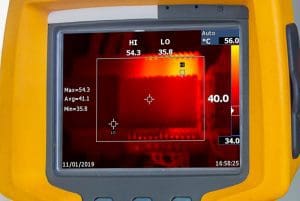 There are two ways for an amplifier to protect itself if it gets too hot. The most common mode is for the amp to stop playing music so that the power supply and output switching devices can cool off. The second option is for the amp to reduce the output signal so that less heat is created. While it’s nice that your music won’t stop playing, most consumers tend to try and turn the volume up higher when the music gets quieter. Eventually, amplifiers that roll back power will go into a state of full protection and shut themselves down to protect components.
If you live in an area that gets hot during the summer, choosing an amplifier with adequate cooling from a large heatsink or a fan is a good idea. Cramming a tiny little amp into the corner of your trunk or cargo area may not be the best choice in this situation.
Visit Your Local Mobile Enhancement Retailer Today
If you are interested in upgrading the audio system in your car, truck or SUV, purchasing a new amplifier will be a fundamental part of the process. Your local specialist car stereo shop can help you wade through the hundreds of amplifier options on the market to find a solution that sounds amazing and works with your budget and performance expectations.
This article is written and produced by the team at www.BestCarAudio.com. Reproduction or use of any kind is prohibited without the express written permission of 1sixty8 media.
