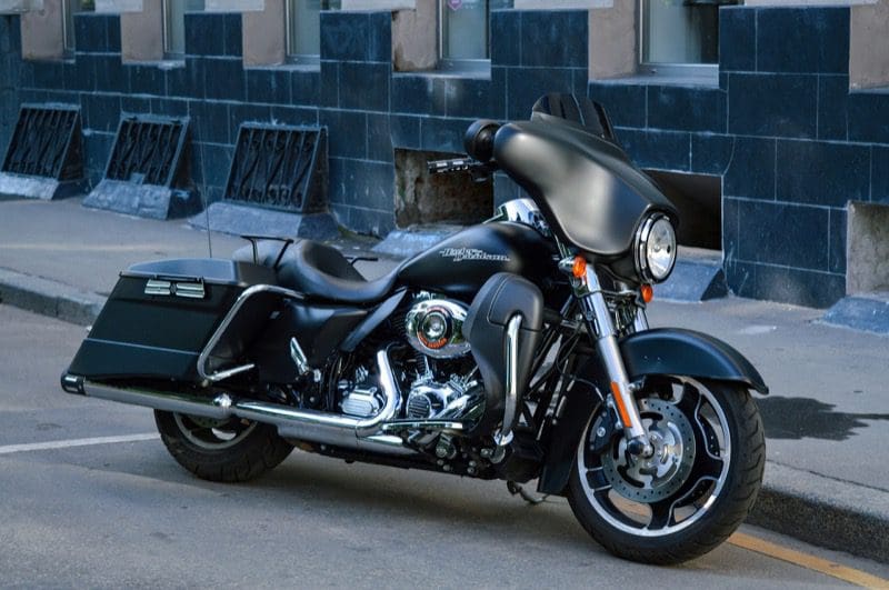
 It’s the middle of the summer, and motorcycle enthusiasts are on their way to the Sturgis Rally for 10 days of music, food and motorcycle fun. One of the fastest growing categories in the mobile electronics industry has been motorcycle audio upgrades. In this article, we’ll provide a few tips and suggestions to ensure that your investment in new audio equipment for your bike will last you for years and sound great.
Where to Buy Motorcycle Audio Upgrades
 We can’t even fathom the number of audio system upgrades we see installed at big meets and rallies like Daytona, Sturgis, Laconia and Myrtle Beach. While leaving your pride and joy with the guys in a booth or trailer to upgrade your stereo while you grab lunch or dinner sounds incredibly convenient, occasionally long-term issues dramatically reduce the value of this purchasing option.
After-Sale Service
Whether you buy a new radio, a set of speakers, an amplifier or a complete audio upgrade solution, those products are backed by a manufacturer’s warranty against failure due to defects. In most cases, if you get a little overzealous with the volume control and damage a speaker, these manufacturers will typically provide you with a replacement. You will need to provide a receipt showing that the products were purchased from and installed by an authorized dealer to get that replacement.
If you have questions or concerns about the system a week after the show, who is going to help you out? What if there is a buzz or rattle from one of the speakers? Is it the installation? Is it a damaged or defective speaker? Working with a store that you can go and visit for help can save a lot of headaches.
Audio System Tuning and Configuration
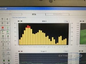
In the case of any worthwhile motorcycle audio upgrade, you are going to need an amplifier to drive the speakers so that they will play loudly enough to drown out your “loud pipes save lives” exhaust system. Unless the amplifier is specifically designed for the exact make and model of bike you own, it has to be set up properly to ensure you won’t damage your new speakers. Mobile electronic specialist retailers operating from a brick-and-mortar location typically have tools like oscilloscopes or a distortion detector to make sure the system is configured properly. Setting up an amplifier is a very important step and is often overlooked. If you can’t turn your audio system up to at least 85 percent of the maximum volume, it wasn’t set up correctly.
Motorcycle Care and Protection
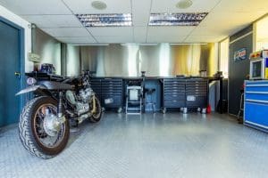 When you pull up to a shop to have your motorcycle audio system upgraded, you can be assured that the bike will be treated like royalty when it’s in their possession. A quality shop will have a storage rack covered in carpet or a blanket for your fairing, saddlebags, windshield or any other delicate parts that need to be removed to upgrade the bike. Many shops apply protective films over painted surfaces like fuel tanks and bumpers. We’ve heard stories where a scratch on a CVO Harley gas tank cost more than $1,000 to repair. Working outdoors doesn’t always provide the space to protect your bike from damage.
Depending on the components you choose for your audio system upgrade, the shop may have to fabricate a mounting bracket or adapter. With your bike in their installation bay, they can go back and forth between the wood shop or fabrication area, so they don’t have to “build” parts near your bike.
Wiring and Hardware Attention to Detail
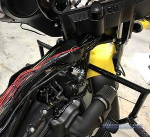
Motorcycles produce a lot of vibrations while cruising down the interstate or idling at a traffic light. This intense motion can wreak havoc with electrical connections that aren’t both mechanically secure and properly protected. Look for a shop that ensures each connection is made in a way that offers a solid physical joint between the two wires. Twisting and taping electrical connections is not recommended, and quick-connects like 3M Scotchloks can cause wires to break and systems to malfunction. Most shops choose to solder connections and wrap them in high-quality vinyl electrical tape or protect them with heat-shrink tubing. Once the connections are complete, the wiring is bundled together neatly and made into a harness with zip ties or automotive grade cloth and fleece tapes. If the audio installation doesn’t look like it is something that rolled off the manufacturer’s assembly line, you’ll want to get it checked.
Two other important factors when it comes to motorcycle sound system upgrades are reliability and serviceability. If speakers need to be to screwed into mounting adapters, the shop should be using stainless-steel hardware so that the fasteners won’t rust. If you have added speakers to a saddlebag, there should be a service loop or electrical connector in the system so that you or your mechanic can remove the bag for service without having to cut or undo any wiring.
Choosing Motorcycle Audio Equipment
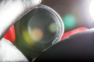
There are hundreds of brands in the mobile electronics industry. About a dozen of them produce speaker solutions designed specifically for motorcycle applications. When you go shopping for speakers, you will want to choose a solution that not only sounds great, but that will last. Motorcycles aren’t like cars or trucks. The speakers are directly exposed to the harsh UV energy from the sun and, if they aren’t constructed from the right materials, will dry out and crack. Look for speakers with water- and UV-exposure compatible materials, so you know your investment will last.
Factory Radio Integration Options
The 2014 and newer Harley-Davidson Boom! Box infotainment system has a lot of features. It also happens to have an elaborate equalizer built into it that changes based on the number of speakers and the exact features of the audio system you choose. When you upgrade the factory H-D speakers to something that sounds better and handles more power, that factory-selected equalization curve works against you and in most cases, the system sounds worse instead of better.
There are two options for dealing with factory-installed Harley source units. The installation technician in a quality shop will have a module that allows them to reflash your radio to an EQ option that offers a smooth and natural response. A second option and one that offers even more flexibility regarding the final performance of the audio system is to include a compact digital signal processor (DSP) in the system design. The installation technician can compensate for the factory EQ curve AND fine-tune the performance of your sound system to suit your listening preferences. If you opt for the DSP route, the installer will need to set up a microphone to tune the audio system. The background noise at a meet or rally would make this process impossible.
Spend Your Money Wisely
One last thought on audio system upgrades for any application. We have different budgets and different listening preferences. With that said, better products almost always sound better. This doesn’t mean you have to spend thousands of dollars upgrading your speakers and amplifiers, but we recommend avoiding stop-gap purchases that will “last until you can afford something better.” Spend your money once on good equipment and it will serve you for years and years.
We hope you have learned something from this article. Now, get off your phone or computer, hop on your motorcycle and take a ride over to your local mobile enhancement retailer and ask them about upgrading your audio system. If you plan things properly, you’ll have a great audio system to enjoy on the ride TO the next meet or rally.
Sturgis photo By Chris Heald (Sturgis) [CC BY 2.0 (https://creativecommons.org/licenses/by/2.0) or CC BY 2.0 (https://creativecommons.org/licenses/by/2.0)], via Wikimedia Commons
This article is written and produced by the team at www.BestCarAudio.com. Reproduction or use of any kind is prohibited without the express written permission of 1sixty8 media.
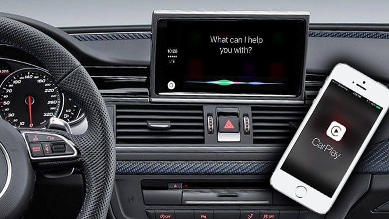 Apple CarPlay and Android Auto smartphone integration
  These infotainment solutions require two components to provide you with Internet-connected voice recognition access to your music, navigation and communication functions. First and foremost, the source unit in the vehicle needs to have the software built in. Including
  Up until recently, the connection between your phone and the radio for CarPlay and Android Auto has used a USB cable. With the introduction of wireless connectivity, things have changed. A Wi-Fi connection between your source unit and your smartphone replaces the wired connection for reliable, high-speed communication. Initially, a little more setup is required to get your smartphone and radio talking, but once configured, everything operates intuitively.
 In November 2017, Google announced the ability for devices running Android to run Android Auto as a stand-alone app without the need for an aftermarket source unit. At CES 2018, several aftermarket manufacturers announced they would include wireless Android Auto connectivity on their new source units.
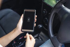 There are have been many discussions about the benefits and drawbacks of wireless connectivity. The biggest point of debate is around phone charging. In most cases, drivers take advantage of the ability to charge their phones when they get in their vehicles as they travel. For most people, this requires that the USB cable is connected to their phone. With that said, the Apple iPhone 8, 8 Plus and X include wireless charging. On the Android side, recent devices from Samsung, LG, Google, Microsoft and Blackberry include wireless charging.
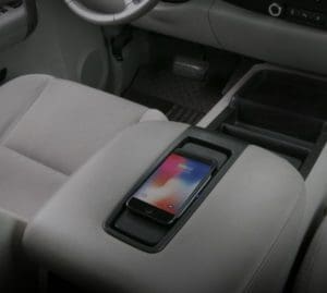 Flipping back to the cons side of the debate, you need a wireless charging base in your vehicle to take advantage of the wireless charging feature. Vehicles from Audi, BMW, Chrysler, Ford, Honda, Mercedes-Benz, Toyota, Volkswagen and Volvo include Qi compatible charging solutions. Qi is the standard for wireless charging for Apple devices.
 Back over accidents are responsible for more than 200 deaths and 12,000 injuries each year. The US Congress passed a law in 2008 that would enact measures to use technology to prevent accidents like these. After years of delays, the US Department of Transportation finally announced that new cars must come with a backup camera.
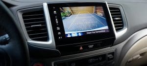 In the simplest of terms, a
  Most factory-installed cameras are mounted above the license plate on a car or in the handle or tailgate emblem of a truck. Aftermarket camera solutions are available to mimic these installation locations. Many vehicles like the Mercedes Sprinter, Ford F-150 and GMC Silverado and Chevy Sierra have aftermarket solutions that look identical to factory offerings. The cameras are water resistant and carry an IP66 (or higher) dust and water intrusion rating. This IP rating means that the cameras can withstand going through the car wash or exposure to the everyday challenges Mother Nature throws their way. Universal cameras are available in surface and flush mount applications. Your mobile enhancement retailer can help you choose the right style for your application.
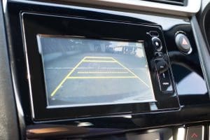 If your car or truck came with a color display for the factory radio or infotainment system, there are many companies that offer premium integration modules that allow the image from the backup camera to be displayed on this screen. Using a factory screen is the most integrated of solutions and truly mimics a factory-installed system.
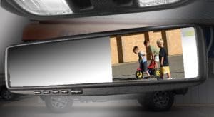 If your vehicle doesn’t have a color screen, another popular option to display a camera image is a replacement rearview mirror that features an integrated color display. When the camera is not in use, the mirror looks normal and will show you what is happening behind your vehicle. When you put the transmission in reverse, a compact LCD screen shines through the mirrored surface to display the camera image. While typically small in size (around 4 inches diagonally), they work very well and are quite popular.
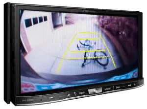 A popular upgrade for older vehicles is to replace the
 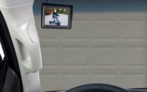 If none of the above options suit your application or you require a larger screen, then consider having a stand-alone monitor installed in your vehicle. Commercial applications such as tow trucks, snow plows, garbage trucks, recycling trucks and delivery vehicles often choose a stand-alone monitor. The image is large, and the unit can be placed in a convenient location.
 Many luxury vehicles combine a
 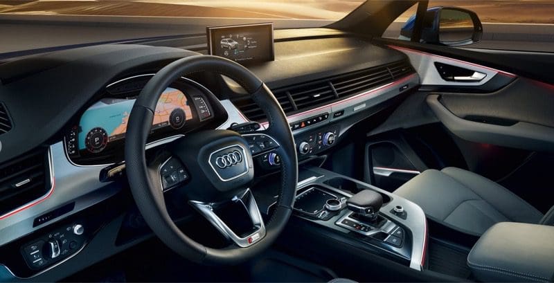 Did you know that you can get great sound in your car or truck using your
 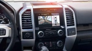 Fewer and fewer cars today have radios that only play music. They show
 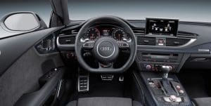 In the good old days, factory audio systems included a radio, a simple analog amplifier and speakers. If you had a luxury vehicle, the manufacturer may have opted to include a subwoofer for a little more (but still not enough) bass. The radio was a simple affair with a tuner, CD player, auxiliary input and maybe a USB port and satellite radio connection. The output of the radio either powered the speakers in the car directly or fed a signal to a small amplifier.
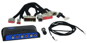 Let’s look at three common upgrades that mobile electronics retailers across the nation perform every day. Since 2009, the Ford F-150 has come equipped with an amplifier in the back of the truck that includes the master volume control for the system as well as equalization and crossovers for the speakers. Upgrading this popular vehicle required summing audio signals coming out of the amp back together and removing signal processing.
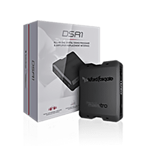 Another popular audio system upgrade interface is the iDatalink Maestro DSR1. Automotive Data Solutions partnered with the audio experts at Rockford Fosgate to develop this interface and tuning solution. ADS are experts in the field of CAN communication protocols, thanks to their experience with remote car starter integration modules.
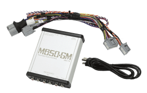 NAV-TV has created an impressive solution that is compatible with Chevy, GMC and Cadillac vehicles with the MyLink and Cue-equipped 4-inch (IO4) and 8-inch (IO5/IO6) source units. This interface connects to the MOST (Media Oriented System Transport) digital signal that runs from the factory radio to the amplifier in these vehicles to extract six channels of full-bandwidth audio that is free from equalization or signal delay.